
Diffusely-reflecting polarizer having nearly isotropic continuous phase

a polarizer and diffusely reflecting technology, applied in the field of diffusely reflecting polarizers, can solve the problems of poor adhesion between inorganic particles and polymer matrix, and inability to achieve optical properties

Inactive Publication Date: 2009-09-01
SKC HAAS DISPLAY FILMS CO LTD
View PDF13 Cites 10 Cited by
  • Summary
  • Abstract
  • Description
  • Claims
  • Application Information

AI Technical Summary

Benefits of technology

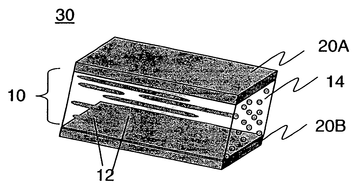
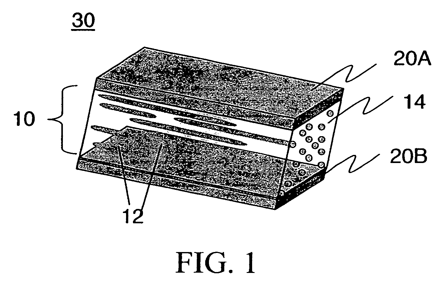
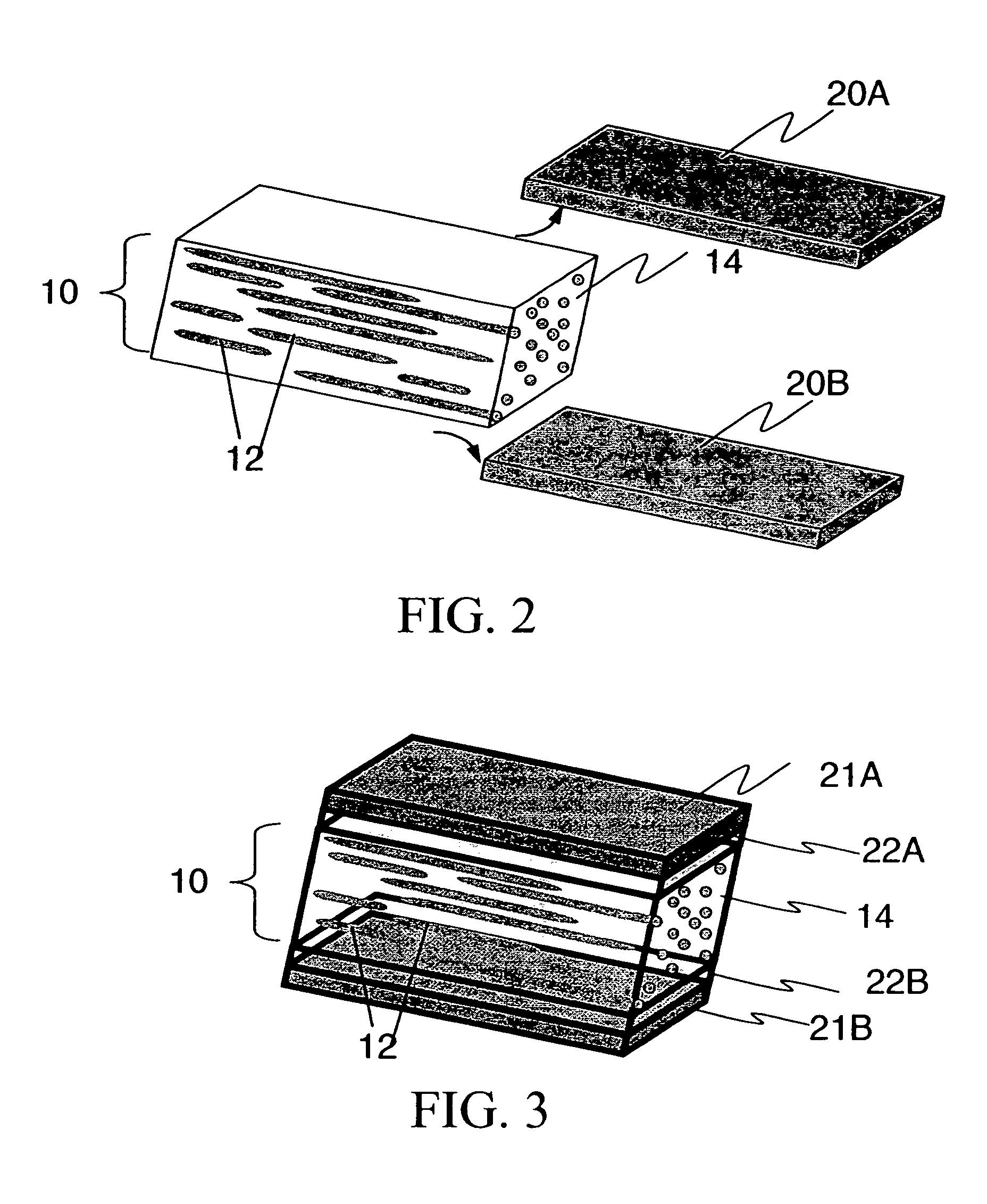
"The patent describes a special type of polarizer that can scatter light in a way that reduces glare and improves image quality. The polarizer is made up of two different polymers that have different properties. The first polymer is smooth and has low birefringence, while the second polymer has a slightly different index of refraction. When these polymers are mixed together, they scatter light in a way that reduces glare and improves image quality. The invention also provides a method for making this polarizer and a way to use it in a liquid crystal display."

Problems solved by technology

However, optical films made from polymers filled with inorganic inclusions suffer from a variety of infirmities.
Typically, adhesion between the inorganic particles and the polymer matrix is poor.
Consequently, the optical properties of the film decline when stress or strain is applied across the matrix, both because the bond between the matrix and the inclusions is compromised, and because the rigid inorganic inclusions may be fractured.
Furthermore, alignment of inorganic inclusions requires process steps and considerations that complicate manufacturing.
Stretching of the material reportedly results in a distortion of the liquid crystal droplet from a spherical to an ellipsoidal shape, with the long axis of the ellipsoid parallel to the direction of stretch.
However, optical films employing liquid crystals as the disperse phase are substantially limited in the degree of refractive index mismatch between the matrix phase and the dispersed phase.
Furthermore, the birefringence of the liquid crystal component of such films is typically sensitive to temperature.
However, due to their liquid crystal nature, films of this type would suffer from the infirmities of other liquid crystal materials discussed above.
A voltage across the electrodes produces an electric field which changes the birefringent properties of the liquid crystal material, resulting in various degrees of mismatch between the refractive indices of the fibers and the liquid crystal.
However, the requirement of an electric or magnetic field is inconvenient and undesirable in many applications, particularly those where existing fields might produce interference.
The refractive index mismatch between the void and the polymer in these “microvoided” films is typically quite large (about 0.5), causing substantial diffuse reflection.
However, the optical properties of microvoided materials are difficult to control because of variations of the geometry of the interfaces, and it is not possible to produce a film axis for which refractive indices are relatively matched, as would be useful for polarization-sensitive optical properties.
Furthermore, the voids in such material can be easily collapsed through exposure to heat and pressure.
As a result, such films have seen limited use for optical applications where optical diffusion is desirable.

Method used


Image

  • Diffusely-reflecting polarizer having nearly isotropic continuous phase
  • Diffusely-reflecting polarizer having nearly isotropic continuous phase
  • Diffusely-reflecting polarizer having nearly isotropic continuous phase

Examples


example 1

[0056]Pure continuous phase polymers Topas 8007, SB, Zylar 631, PETG 6763, and PCTG 5445 were coextruded with protective layers PET or PEN, and were stretched under the same conditions as the blends comprising the continuous and the disperse phases, i.e., at the same stretching temperature and the same stretching ratio. The skin layers were then peeled off. The refractive indices npara, nperp, and nz of each core layer consisting of pure amorphous polymer were then measured using the Metricon Prism Coupler 2010 from Metricon Corporation determined at the wavelength of 633 nm. The refractive indices npara, nperp, and nz correspond to the directions parallel to the stretching direction, perpendicular to the stretching direction, and along the sheet thickness direction, respectively. All the three indices nperp, and nz are very close to each other, with the difference between any two of them is less than 0.02, and the difference in most cases was smaller than 0.005. The refractive indi...

example 2

[0057]70% wt. Zylar 631 as the continuous phase polymer, 30% wt. PEN as the dispersed polymer, protective layer PEN, stretched 5× in the extruded film direction at a temperature of 125° C. This sample had an FOM value of 1.66 and had a total reflectivity of 83%, a diffuse reflectivity of 71% and a specular reflectivity of 12% (all measured at 550 nm).

example 3

[0058]60% wt. PETG 6763 as the continuous phase polymer and 40% wt PEN as the dispersed polymer, stretched 5× in the direction perpendicular to the extruded film direction at a temperature of 132° C. This sample had an FOM value of 1.43 and had a total reflectivity of 73%, a diffuse reflectivity of 62% and a specular reflectivity of 11% (all measured at 550 nm).


PUM


Abstract

The present invention provides a diffusely-reflecting polarizer havinga first polymer which is amorphous and having a birefringence of less than about 0.02 and a second polymer, the first polymer being a continuous phase, and the second polymer being a disperse phase whose index of refraction differs from said continuous phase by greater than about 0.05 along a first axis and by less than about 0.05 along a second axis orthogonal to said first axis;wherein the diffuse-reflectivity of said first and second polymers taken together along at least one axis for at least one polarization state of electromagnetic radiation is at least about 50%, the diffuse transmittance of said first and second polymers taken together along at least one axis for at least one polarization state of electromagnetic radiation is at least about 50%.

Description

CROSS-REFERENCE TO RELATED APPLICATION[0001]This application claims priority of Provisional Application 60 / 810,884 filed Jun. 5, 2006, the contents of which are incorporated herein by reference.FIELD OF THE INVENTION[0002]This invention relates to a diffusely-reflecting polarizer comprising a film having a first continuous phase and a second disperse phase, the continuous phase being amorphous and nearly optically isotropic, and a method of making such a diffusely-reflecting polarizer.BACKGROUND OF THE INVENTION[0003]Reflective polarizing films transmit light of one polarization and reflect light of the orthogonal polarization. They are useful in an LCD to enhance light efficiency. A variety of films have been disclosed to achieve the function of the reflective polarizing films, among which diffusely reflecting polarizers are more attractive because they may not need a diffuser in a LCD, thus reducing the complexity of the LCD. U.S. Pat. Nos. 5,783,120 and 5,825,543 teach a diffusel...

Claims


Application Information

Patent Timeline
Patent Type & Authority Patents(United States)
IPC IPC(8): G02B5/30
CPCG02B5/0236G02B5/0257G02B5/3083G02B5/3008G02B5/0284G02B5/02G02B5/30
Inventor MI, XIANG-DONGGREENER, JEHUDAANDERSON, CHARLES C.LANEY, THOMAS M.
Owner SKC HAAS DISPLAY FILMS CO LTD
Learn More