Multiplex signal error correction method and device

a multi-signal and error correction technology, applied in the field ofofdm-type telecommunication signals, can solve the problems of sensitive dependence of the correct decoding of ofdm signals on the receiver end, the inability to use pilot channels for channel estimation, and the inability to use pilot subcarriers in the specified standards for channel estimation. , to achieve the effect of reducing a phase error

Inactive Publication Date: 2009-09-01
IHP GMBH INNOVATIONS FOR HIGH PERFORMANCE MICROELECTRONICS LEIBNIZ INST FUR INNOVATIVE
View PDF19 Cites 2 Cited by
  • Summary
  • Abstract
  • Description
  • Claims
  • Application Information

AI Technical Summary

Benefits of technology

[0013]The technical object of the invention is to provide a fast method of reducing a phase error in a received signal, which is caused by at least one error source, and a suitably designed apparatus for carrying out the method.
[0014]That object is attained by a method of reducing a phase error caused by a plurality of error sources in a signal which is present in a digital frequency representation in the form of a sequence of a plurality of digital partial signals which are associated with a number of subcarriers (k) of a carrier, with the steps which are effected for each partial signal:

Problems solved by technology

The standards “IEEE 802.11a” and “Hiperlan / 2” for wireless communication in networks in the 5 GHz frequency range do not permit use of the pilot channels for channel estimation.
In general terms however the pilot subcarriers cannot be used in the specified standards for channel estimation.
Correct decoding of OFDM signals on the receiver end is delicately dependent on the efficiency of the synchronization unit of the receiver.
Frequency offsets produce errors which lead to incorrect decoding of the received signal.
The correction of a phase error in the time domain has the disadvantage of a great delay for the signal.
The use of phase locked loops for phase estimation additionally signifies a high level of circuitry complication and expenditure.
That gives rise to errors in the decoding operation, which can result in a data communication crashing.
Those circuits cause a severe delay in terms of signal decoding.

Method used


Image

  • Multiplex signal error correction method and device
  • Multiplex signal error correction method and device
  • Multiplex signal error correction method and device

Examples


Embodiment Construction

[0020]FIG. 1 is a simplified block circuit diagram showing a per se known OFDM receiver in the form of a heterodyne radio frequency down-converter 10, hereinafter referred to for brevity as the down-converter.

[0021]The down-converter 10 has an antenna 12. Connected downstream of the antenna is a band pass filter 14 and a low-noise pre-amplifier 16 (referred to as a low-noise amplifier or LNA).

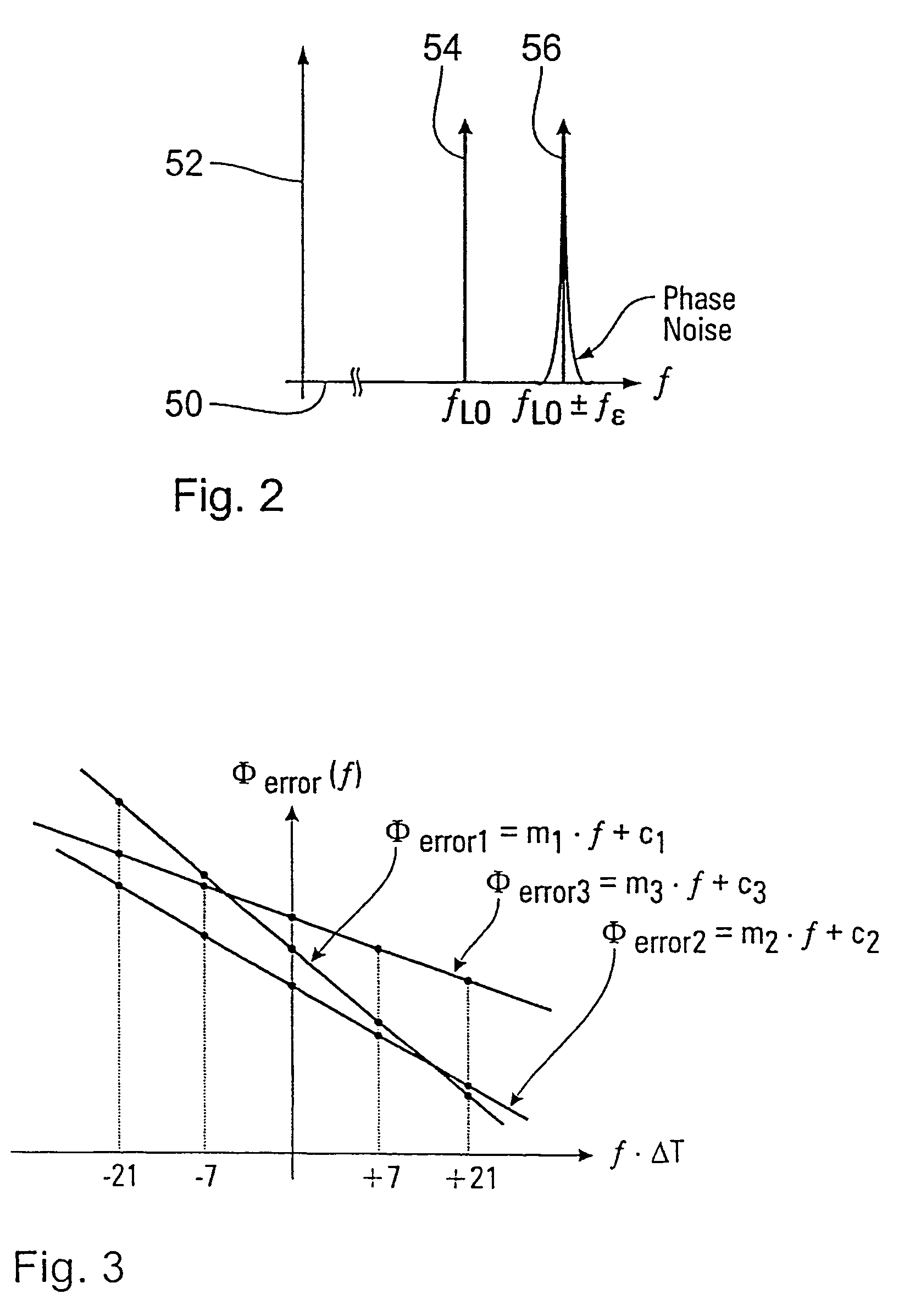
[0022]A first mixer stage which is connected at the input side to the output of the pre-amplifier has a frequency mixer 18 and a local oscillator 20. The frequency of the oscillation produced by the local oscillator 20 is the difference of the carrier frequency Fc of the oscillation received by the down-converter at its antenna and an intermediate frequency fIF (referred to as IF). The frequency mixer multiplies the filtered and pre-amplified signal by the frequency of the local oscillator 20. Due to tuning inaccuracies in the local oscillator 20, a frequency offset of the frequency of the loca...


PUM


Abstract

A method of reducing a phase error caused by a plurality of error sources in a signal in the form of a sequence of a plurality of digital partial signals associated with a number of subcarriers (k) of a carrier, the method including, for each partial signal: equalization of the partial signal (Y(i,k)), estimation of the phase error of the equalized partial signal (X(i,k)), and correction of the estimated phase error of the equalized partial signal. One embodiment provides the equalization with elimination of an accumulation of a phase error over the sequence of the partial signals. In addition the estimation includes detecting a plurality of predetermined pilot signals and determining a phase correction factor on the basis of the detected pilot signals, with at least one multiplication operation carried out solely by means of shift and adding operations. A corresponding apparatus is also described.

Description

CROSS REFERENCE TO RELATED APPLICATIONS[0001]This application is for entry into the U.S. national phase under §371 for International Application PCT / EP03 / 11193 having an international filing date of Oct. 9, 2003, and from which priority is claimed under all applicable sections of Title 35 of the United States Code including, but not limited to, Sections 120, 363 and 365(c), and which in turn claims priority under 35 USC §119 to German Patent Application No. 102 48 507.0-42 filed on Oct. 11, 2002.TECHNICAL FIELD[0002]Reducing errors in telecommunications, and more particularly in OFDM type telecommunication signals.BACKGROUND ART[0003]The multi-carrier method OFDM (orthogonal frequency division multiplex) is becoming more widespread as time goes by. It is used for digital radio (digital audio broadcasting or DAB), digital television (digital video broadcasting or DVB) and for local radio networks (high performance local area network or Hiperlan).[0004]OFDM differs from single-carrier...

Claims


Application Information

Patent Timeline
Patent Type & Authority Patents(United States)
IPC IPC(8): H04L7/00H04L25/02H04L25/03H04L27/26
CPCH04L25/0204H04L27/2675H04L27/2657H04L25/022H04L2025/03414
Inventor TROYA, ALFONSOKRSTIC, MILOSMAHARATNA, KOUSHIK
Owner IHP GMBH INNOVATIONS FOR HIGH PERFORMANCE MICROELECTRONICS LEIBNIZ INST FUR INNOVATIVE
Why Eureka
Try Eureka