
Shredding apparatus and method of clearing land

a technology of cutting drums and cutting teeth, applied in the field of cutting drums, can solve the problems of tremendous radial and axial stress loads on the cutting teeth, the drive shaft, the drum, etc., and achieve the effect of increasing the length of the in-service time interval

Inactive Publication Date: 2009-09-08
BENNINGTON JOHN W
View PDF2 Cites 42 Cited by
  • Summary
  • Abstract
  • Description
  • Claims
  • Application Information

AI Technical Summary

Benefits of technology

[0004]It is an objective of the present invention to increase the length of the in-service time intervals for a land-clearing shredder.
[0005]Another objective is to reduce the time and expense for maintenance of a shredder.
[0006]Yet another objective is to provide a shredder capable of quickly and effectively clearing large areas of land.

Problems solved by technology

Accordingly, the shredding operation places tremendous radial and axial stress loads on the drum, the cutting teeth, the drive shaft, and other component parts associated with the drum assembly and its operation.

Method used


Image

  • Shredding apparatus and method of clearing land
  • Shredding apparatus and method of clearing land
  • Shredding apparatus and method of clearing land

Examples


Embodiment Construction

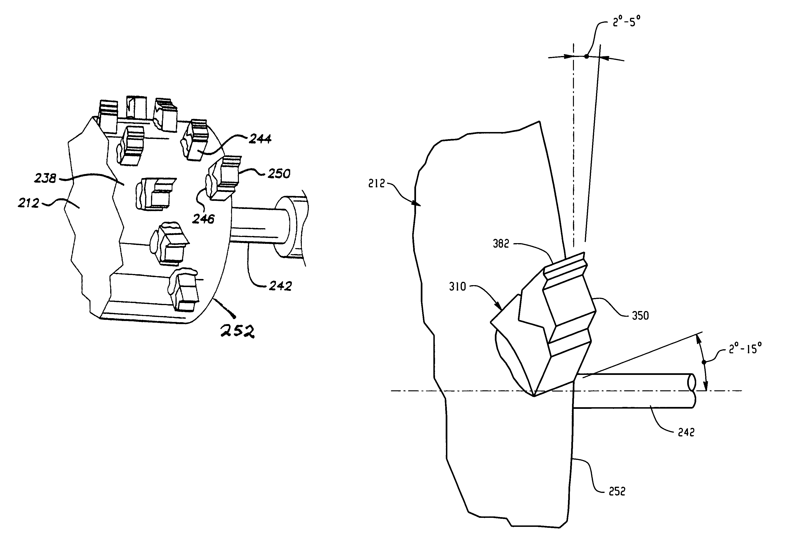
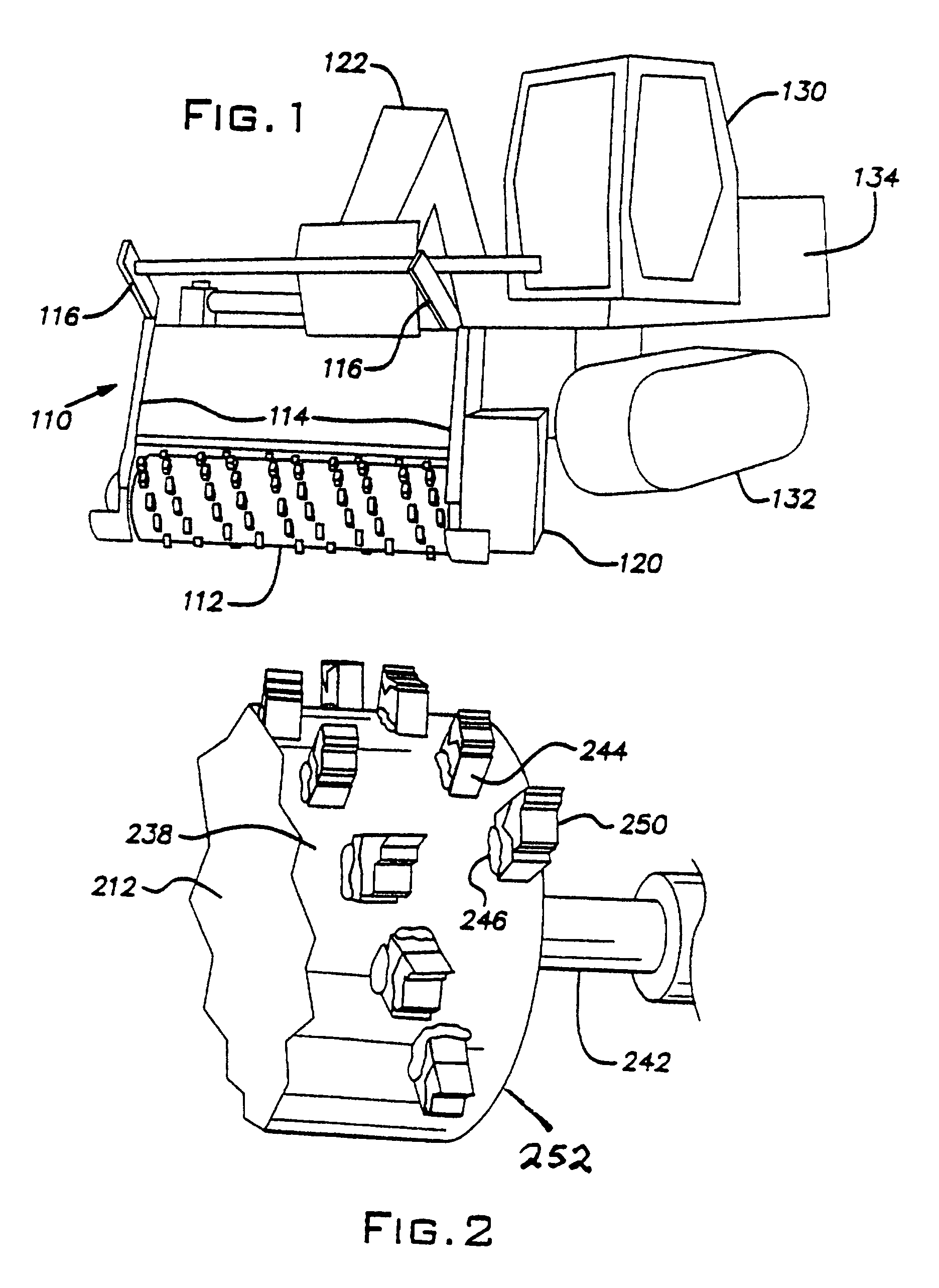
[0017]The present invention relates to a boom end shredding drum mounted on a shaft driven by a suitable power source. For purposes of illustration, the shredder may comprise a 10 inch to 20 inch diameter cutter drum between 40 inches and 80 inches in length, with between 35 and 110 cutter teeth mounted in blocks on the drum surface. The drum is mounted on a shaft driven by an internal combustion engine, such as a 200 or 275 horsepower Cummins diesel engine. The engine is directly coupled to the shaft onto which the drum is mounted, or it is joined to the shaft through a series of belts and / or gears. The engine is capable of driving the shredding drum at a rotational speed typically between about 1000 rpm and about 1400 rpm.

[0018]Shredders of this type are manufactured by Sneller Machine Co., Cleveland, Ohio, and are referred to as the Sneller Shredder 275. The drive shaft rotates in two sets of roller bearings. Because of the encounters with miscellaneous debris during shredding, t...


PUM


Abstract

A shredding apparatus utilizes a cylindrical drum adapted for quickly and effectively clearing large tracts of land. Several blocks are positioned in two spiral rows on the periphery of the drum and are secured to the drum by welding. The blocks in each row are spaced from one another an axial distance that provides a complete sweep of the land as the drum rotates. Each of the blocks includes a replaceable cutter tooth. The teeth each include a shank that is anchored in a hole in each block. At least one block is mounted along each edge of the drum at a slight outward angle between about 2°, and about 15°, and is tilted outwardly between about 2° and about 5° so that its corresponding tooth provides protection of the drum edge. All of the remaining blocks are mounted so that the teeth are parallel with the drum axis.

Description

CROSS-REFERENCE TO RELATED APPLICATIONS[0001]This application is a continuation-in-part of U.S. patent application Ser. No. 11 / 207,494 filed Aug. 19, 2005, now U.S. Pat. No. 7,281,676 B2 issued Oct. 16, 2007 and entitled SHREDDING APPARATUS AND METHOD OF CLEARING LAND.FIELD OF THE INVENTION[0002]This invention relates to the field of cutting drums useful for shredding small trees, shrubs and undergrowth. More specifically, it relates to a shredder assembly, the component parts thereof, and the use of a shredder in land clearance.BACKGROUND OF THE INVENTION[0003]Typically, powered devices useful for clearing debris from land may vary in size from small hand held weed trimmers to large rotatable shredding drums capable of rapidly clearing vast tracts of land. These large shredding drums typically have a plurality of cutting teeth disposed circumferentially on their outer surface. A large shredder can be powered by a chain drive, by gears or belts, or by direct drive. It may be mounted...

Claims


Application Information

Patent Timeline
IPC IPC(8): B02C23/00
CPCB02C18/145A01G23/093
Inventor BENNINGTON, JOHN T.BENNINGTON, JOHN W.
Owner BENNINGTON JOHN W
Features
  • Generate Ideas
  • Intellectual Property
  • Life Sciences
  • Materials
  • Tech Scout
  • Unparalleled Data Quality
  • Higher Quality Content
  • 60% Fewer Hallucinations
Learn More