Disk array apparatus and liquid cooling apparatus thereof

a technology of liquid cooling apparatus and disk array, which is applied in the direction of electrical apparatus construction details, electrical apparatus casings/cabinets/drawers, instruments, etc., can solve the problems of deteriorating reliability of disk array apparatus, temperature control in the controller for use of the group of fans, and affecting the cooling performance of disk drives. , to achieve the effect of reducing the increase in the temperature improving the cooling performance of the disk drive, and high density

Active Publication Date: 2009-09-08
GOOGLE LLC
View PDF20 Cites 20 Cited by
  • Summary
  • Abstract
  • Description
  • Claims
  • Application Information

AI Technical Summary

Benefits of technology

[0015]Then, according to the present invention, in particular, an object thereof is to achieve high-capacity and high-speed for a disk array apparatus, installation of disk drives with high density, while enabling an improvement on cooling performances of the disk drives and other electronic apparatuses, which are installed within a housing of the disk array apparatus, thereby reducing an increase in temperature of the disk drive, as well as, reducing the unevenness in temperatures among the disk drives, so as to increase the reliability of the disk drive apparatus and / or the electronic apparatus, and further obtaining a long lifetime thereof.
[0021]As was mentioned in the above, according to the present invention, it is possible to obtain an improvement on the cooling performances of the disk drives, which are contained within the rack of the housing of the disk array apparatus in a large number thereof, and also to reduce an increase of temperature of the disk drives, as well as, an unevenness in temperature among the disk drives; thereby obtaining a long lifetime and also improvement of reliability of the disk drives, and with this, it is possible to achieve installation of the disk drives at high density, and achieving large capacity and high speed of the disk array apparatus, as well. Further, according to the present invention, it is also possible to cool the high-heat generation element, such as, the controller to be installed within the housing of the disk array, with certainty, and thereby enabling an improvement on the reliability of the disk drive apparatus as a whole.

Problems solved by technology

For this reason, if cooling capacity thereof is bad, the temperature of the disk drive goes up, or there are generated unevenness in the temperatures among those plural numbers of disk drives, and as a result thereof, there is possibility of erroneous operations for a long time period and deterioration of reliability of the disk array apparatus.
However, with the conventional art in relation to the Patent Document 1 mentioned above, since there is necessity of providing a sensor on each surface of the disk drives (in more details, on the outer wall), therefore the wiring becomes complex, within the housing, and also there is necessity of providing, as well as, a means for detecting temperature, a controller means for achieving control thereon, accompanying with it, i.e., controllers for a group of fans.
For this reason, further, the temperature control in the controllers for use of the group of fans also comes to be a problem, from a viewpoint for maintaining the reliability of the disk array apparatus.
Also, with the conventional art in relation to the Patent Document 2 mentioned above, there is no such necessity of provision of the controllers for the group of fans and the controls thereof, as was mentioned above; therefore it is possible to improve the reliability of an equipment, but on the contrary thereto, there is another problem of taking a long time for adjusting the flow passages for the cooling winds within the housing, in particular, when designing the apparatus.
For this reason, with the conventional art in relation to the Patent Document 3 mentioned above, the controller mentioned above brings about an increase of cost, the control thereof becomes complex, and further problems occur with the reliability of the controller itself.

Method used


Image

  • Disk array apparatus and liquid cooling apparatus thereof
  • Disk array apparatus and liquid cooling apparatus thereof
  • Disk array apparatus and liquid cooling apparatus thereof

Examples


Embodiment Construction

)

[0029]Hereinafter, embodiments according to the present invention will be fully explained by referring to the attached drawings. However, hereinafter, explanation will be made on an example of electronic apparatuses, into which the present invention is applied, in particular, an example of applying the present invention into a disk array apparatus.

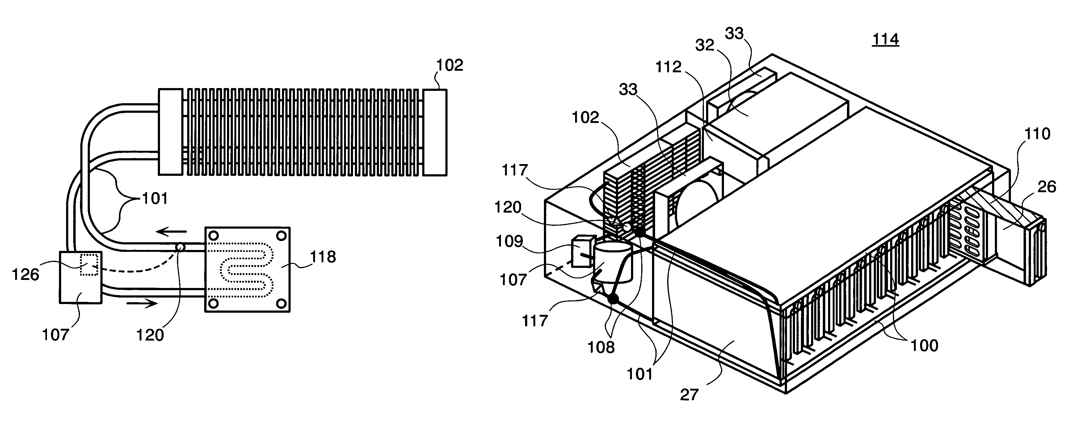
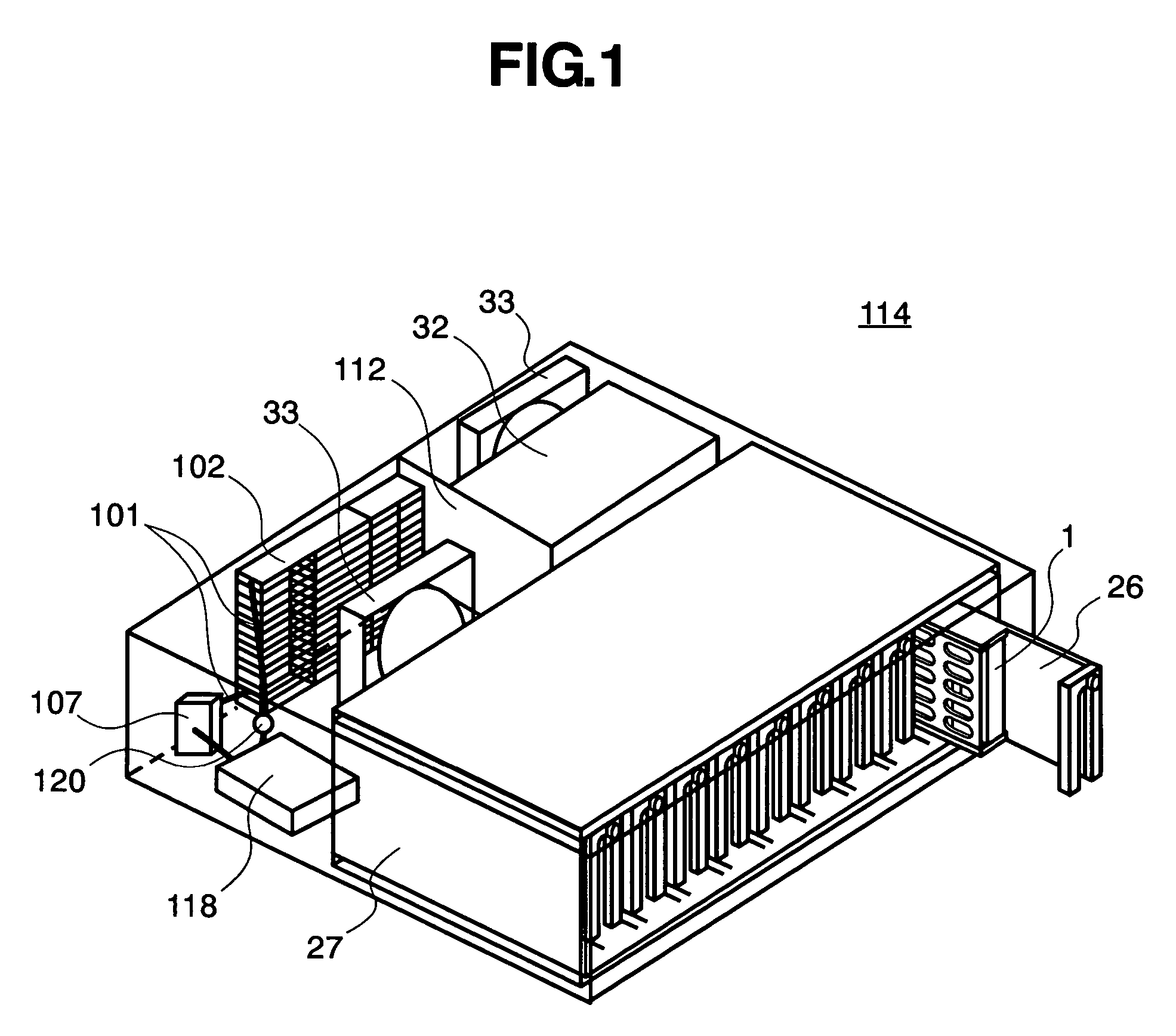
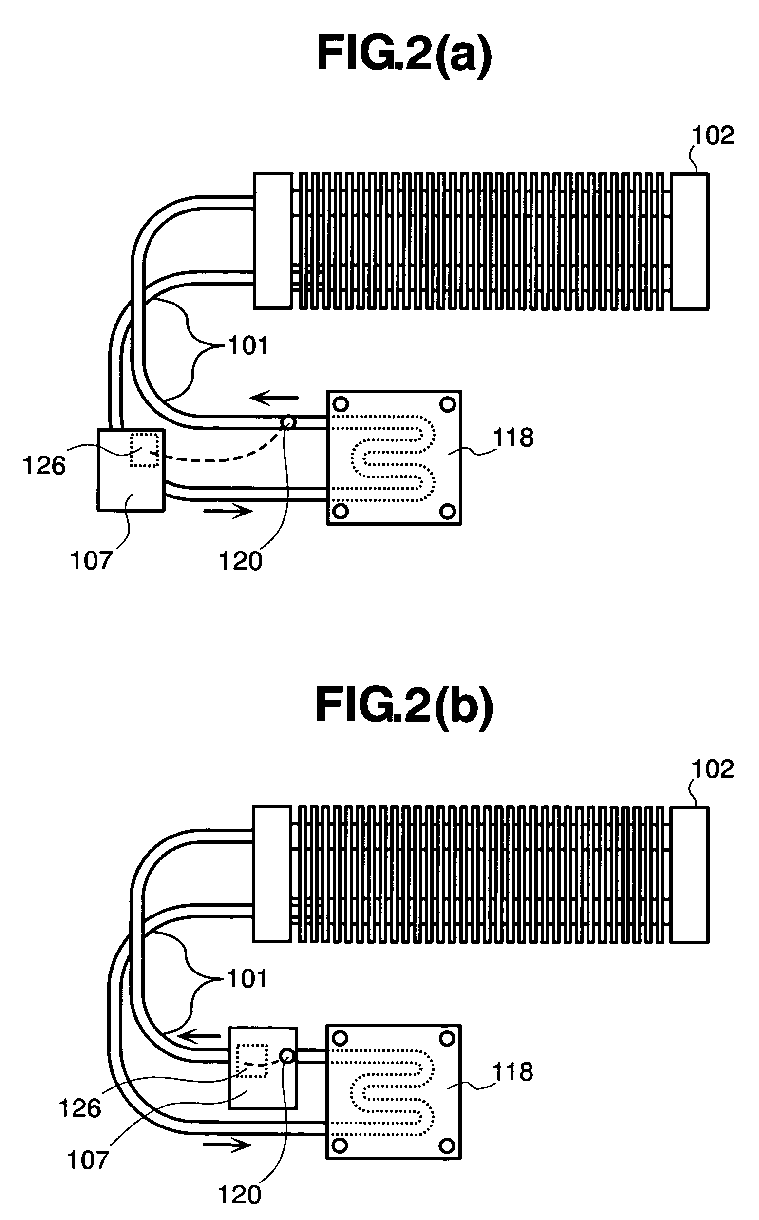
[0030]Detailed explanation will be made about an embodiment of the present invention, by referring to FIGS. 1 to 6 attached herewith. First of all, FIG. 1 shows the entire structure of a unit housing 114 of a disk array apparatus, into which the present invention is applied, and this unit housing stores or contains therein a large number of disk main bodies 1, as well as, disk drives 26 (the detailed structures thereof is shown in FIG. 5), which include package boards 2 for control (not shown in the figure) and a canister 7 (not shown in the figure), with the disk drives 26 being aligned (in the present example, being aligned in the verti...


PUM


Abstract

A liquid cooling apparatus for use in a disk array apparatus which contains a plural number of units having a disk drive inside of a housing and disposed within a rack, including an air-blow fan, a pump for transmitting liquid coolant, a radiator for transmitting heat absorbed into the liquid coolant into outside air, and pipes for connection of the pump and radiator. The liquid cooling apparatus further includes a temperature sensor disposed at a position for detecting temperature of the liquid coolant, which temperature changes in response to electric power consumed within the plural number of disk drives, and a rotation speed of the pump is controlled in dependence upon a detection signal from the temperature sensor.

Description

BACKGROUND OF THE INVENTION[0001]The present invention relates to cooling of a disk array apparatus, installing therein magnetic- or optic-type disk drives in plural pieces thereof, and further, it relates to a liquid cooling apparatus for cooling heat generation, effectively, within such the apparatus with using a liquid coolant therein.[0002]In general, the disk array apparatus is constructed by installing a large number of magnetic- or optic-type disk drives within a housing, for the purpose of increasing reliability of data reservation therein. And, those disk array apparatuses are connected with, through a high-speed network circuit for exclusive use thereof, such as, of an optic-type, etc., for example, to be operated by means of management software; i.e., they are utilized in the form of those disk apparatuses; i.e., the so-called SAN (Storage Area Network), NAS (Network Attached Storage), or an independent RAID (Redundant Array of Inexpensive Disks).[0003]Normally, the disk ...

Claims


Application Information

Patent Timeline
Patent Type & Authority Patents(United States)
IPC IPC(8): H05K7/20G06F1/20
CPCG06F1/206Y02B60/1275G06F2200/201Y02D10/00
Inventor MATSUSHIMA, HITOSHIFUKUDA, HIROSHIYAMANA, SHUNSUKE
Owner GOOGLE LLC
Why Eureka
Try Eureka