Advanced humid air turbine power plant

a technology of humid air turbines and power plants, which is applied in the direction of machines/engines, engine components, mechanical equipment, etc., can solve the problems of condensation of moisture, insufficient heating of gas turbines, and equipment configuration details, so as to reduce condensation of moisture, improve reliability of gas turbines, and reduce the effect of condensation

Active Publication Date: 2009-09-15
MITSUBISHI POWER LTD
View PDF10 Cites 12 Cited by
  • Summary
  • Abstract
  • Description
  • Claims
  • Application Information

AI Technical Summary

Benefits of technology

[0011]It is an object of the present invention to provide, in a power system using humidified air as a coolant for cooling a high-temperature component of a gas turbine, an advanced humid air turbine power plant and a method of operating the power plant, which can suppress condensation of moisture in a cooling channel at the time of load variation, startup and stop of the gas turbine, or in the event of an abnormality in a humidifying line.
[0012]To achieve the above object, in an advanced humid air turbine power plant comprising a compressed air supply pipe for supplying, as a coolant, a part of compressed air generated by a compressor to a high-temperature component of a gas turbine, and a humidified air supply pipe for supplying, as a coolant, a part of humidified air generated in a humidifying tower to the high-temperature component of the gas turbine, the power plant further comprises valves capable of adjusting respective air flow rates in the compressed air supply pipe and the humidified air supply pipe. With this feature, by supplying the compressed air as the coolant in a start up stage, a load increasing stage, a load decreasing stage and a coast down stage, as well as in the event of an abnormality in a humidifying line, condensation of moisture in the coolant can be suppressed and the high-temperature component of the gas turbine can be cooled without imposing a thermal load on it, thus resulting in higher reliability of the gas turbine.
[0013]Also, the power plant of the present invention is featured in opening and closing the valves depending on the rotating speed and load state of the gas turbine, the air temperature at the side of a turbine rotor, and the temperature and humidity of the humidified air measured in the coolant supply pipe. With this feature, when cooling air is switched over from the compressed air to the humidified air or from the humidified air to the compressed air in the start up stage, the load increasing stage, the load decreasing stage and the coast down stage, as well as in the event of an abnormality in the humidifying line, the switching-over of the cooling air can be performed effectively and the reliability of the gas turbine can be increased.
[0014]According to the present invention, in the advanced humid air turbine power plant, it is possible to suppress condensation of moisture in a cooling channel, which is provided to cool the high-temperature component of the gas turbine, in the start up stage, the coast down stage, and the load varying state of the gas turbine.

Problems solved by technology

However, the cooling technique disclosed in the above-cited JP,A 11-257006 does not take into consideration details of the equipment configuration and the operating method, such as what coolant is prepared in what manner in what operating state.
In the start up stage and the load increasing stage of the gas turbine, the gas turbine is not sufficiently warmed up.
Therefore, if the humidified air in the gas turbine is used as the coolant, this gives rise to a possibility that the metal temperature of the cooling channel in the high-temperature component of the gas turbine may be lower than the dew point of the humidified air, thus resulting in condensation of moisture.
The accumulated impurities may cause rotational vibrations or clogging of the cooling channel, and the component may be locally rapidly cooled due to the latent heat of evaporation, thus resulting in erosion.
In the load decreasing stage and the coast down stage of the gas turbine, as the temperature of the gas turbine gradually lowers, there also occur a possibility that the metal temperature of the cooling channel in the high-temperature component of the gas turbine may be lower than the dew point of the humidified air, thus resulting in condensation of moisture.
The condensation of moisture may cause, as in the startup stage, rotational vibrations, clogging of the cooling channel, or erosion.
Further, if the humidified air remains in the cooling channel after the stop of the gas turbine, moisture and oxygen both contained in the residual humidified air may cause oxidization and corrosion of the component.

Method used


Image

  • Advanced humid air turbine power plant
  • Advanced humid air turbine power plant
  • Advanced humid air turbine power plant

Examples


first embodiment

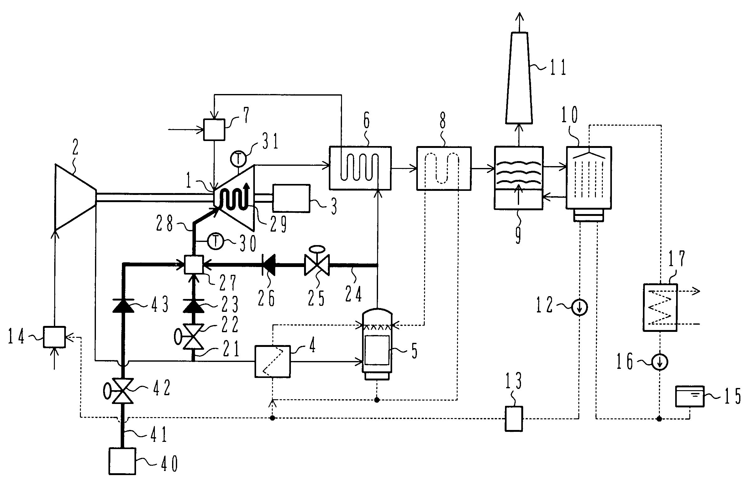
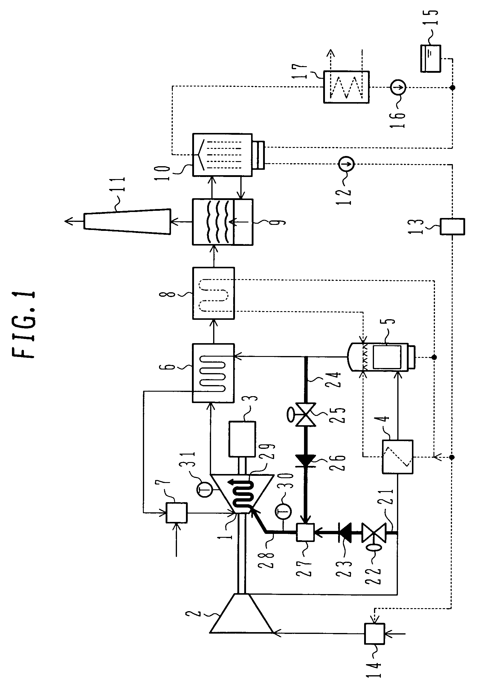
[0024]FIG. 1 is a block diagram of an advanced humid air turbine power plant according to a first embodiment of the present invention. In FIG. 1, a solid line represents a gas passage. The gas passage includes equipment disposed therein and they are collectively referred to as an “air line” in the following description. Also, a dotted line in FIG. 1 represents a water passage. The water passage includes equipment disposed therein and they are collectively referred to as a “humidifying line”. Further, a fat solid line in FIG. 1 represents a coolant passage that is a feature of the present invention. The coolant passage includes equipment disposed therein and they are collectively referred to as a “cooling line” in the following description.

[0025]The air line will first be described below. As shown in FIG. 1, the advanced humid air turbine power plant comprises a gas turbine (GT) 1, a compressor 2, and a generator 3, which are coupled to one shaft. Atmospheric air is supplied to the c...

second embodiment

[0042]FIG. 5 is a block diagram of an advanced humid air turbine power plant according to a second embodiment of the present invention. A description of the same components as those in FIG. 1 is omitted here. While the first embodiment of FIG. 1 utilizes, as the humidified air that is used as air for cooling the high-temperature component of the gas turbine, the humidified air supplied from the humidifying tower 5 to the recuperator 6, this second embodiment utilizes the humidified air having a temperature raised in the recuperator 6. Practically, a humidified air supply pipe 36 is provided to branch a part of the humidified air from an intermediate position of a channel in the recuperator 6. The humidified air branched by the humidified air supply pipe 36 is supplied to the mixer 27 via the humidified air supply valve 25 and the check valve 26.

[0043]The temperature of the humidified air exiting the humidifying tower 5 is lower than the temperature of the compressed air exiting the ...

third embodiment

[0044]FIG. 6 is a block diagram of an advanced humid air turbine power plant according to a third embodiment of the present invention. While the first embodiment of FIG. 1 utilizes, as the compressed air that is used as air for cooling the high-temperature component of the gas turbine, the compressed air supplied from the compressor 2 to the air cooler 4, this third embodiment supplies the compressed air of which temperature has been reduced in the air cooler 4. Practically, a compressed air supply pipe 37 is provided to branch a part of the compressed air to a high-temperature component cooling channel 29 (provided by the cooling air supply air 28) from an intermediate position of a passage through which the compressed air having been cooled in the air cooler 4 is supplied to the humidifying tower 5. The compressed air branched by the compressed air supply pipe 37 is supplied to the mixer 27 via the compressed air supply valve 22 and the check valve 23.

[0045]Immediately after the o...


PUM


Abstract

An advanced humid air turbine power plant capable of suppressing condensation of moisture in a cooling channel, which is provided to cool a high-temperature component of a gas turbine, in a start up stage, a coast down stage, and a load varying state of the gas turbine. In the advanced humid air turbine power plant comprising a compressed air supply line for supplying compressed air generated by a compressor to the high-temperature component of the gas turbine, and a humidified air supply line for supplying humidified air generated in a humidifying tower to the high-temperature component of the gas turbine, the power plant further comprises valves capable of adjusting respective air flow rates in the compressed air supply line and the humidified air supply line. A coolant is switched over from the compressed air to the humidified air in the start up stage and the load increasing stage of the gas turbine, and from the humidified air to the compressed air in the load decreasing stage and the coast down stage, as well as in the event of an abnormality in a humidifying line.

Description

BACKGROUND OF THE INVENTION[0001]1. Field of the Invention[0002]The present invention relates to an advanced humid air turbine power plant including a humidifying line to humidify gas (air) supplied to a gas turbine.[0003]2. Description of the Related Art[0004]In an advanced humid air turbine, combustion gases contain moisture and have a larger heat transfer coefficient and larger specific heat than air due to differences in physical variables therebetween, such as the coefficient of viscosity and the Plandtl number. Therefore, the thermal load in a high-temperature component of the gas turbine, such as a turbine blade, is increased in comparison with an ordinary gas turbine. Correspondingly, the high-temperature component of the gas turbine must be cooled in a stepped-up manner. However, if air cooling is employed as in the ordinary gas turbine, a very large amount of cooling air is required, which results in a lowering of the temperature of a main stream gas and a reduction in the...

Claims


Application Information

Patent Timeline
Patent Type & Authority Patents(United States)
IPC IPC(8): F02C3/30F02C7/16F02C7/18F01D25/12F02C7/143
CPCF02C7/18F02C3/30
Inventor HORIUCHI, YASUHIROMARUSHIMA, SHINYAARAKI, HIDEFUMIHATAMIYA, SHIGEO
Owner MITSUBISHI POWER LTD
Why Eureka
Try Eureka