Multifunctional vacuum manifold

a vacuum manifold and multi-functional technology, applied in the field of multi-functional vacuum manifolds, can solve the problems of inability to program automated equipment, failure to accurately transfer liquid on the deck of a conventional liquid handler, and inability to achieve reproducible automatic transfer

Active Publication Date: 2009-09-15
MILLIPORE CORP
View PDF15 Cites 16 Cited by
  • Summary
  • Abstract
  • Description
  • Claims
  • Application Information

AI Technical Summary

Problems solved by technology

Still, accurate liquid transfer is not possible on the deck of a conventional liquid handler, because the position of the plate in the Z-direction can vary during use.
The amount of movement is too great or variable to be able to program a liquid handling robot to account for the movement, making successful, reproducible automated transfer difficult or impossible.
Similar problems arise with the Sequencing clean-up where the small volume is aspirated off the surface of the membrane.
If the position of the membrane varies then it is not possible to program the automated equipment to aspirate off the surface of the membrane without potentially damaging the membrane surface.
However, in such a design, the spouts are exposed and are thus prone to damage and / or contamination.

Method used


Image

  • Multifunctional vacuum manifold
  • Multifunctional vacuum manifold
  • Multifunctional vacuum manifold

Examples


Embodiment Construction

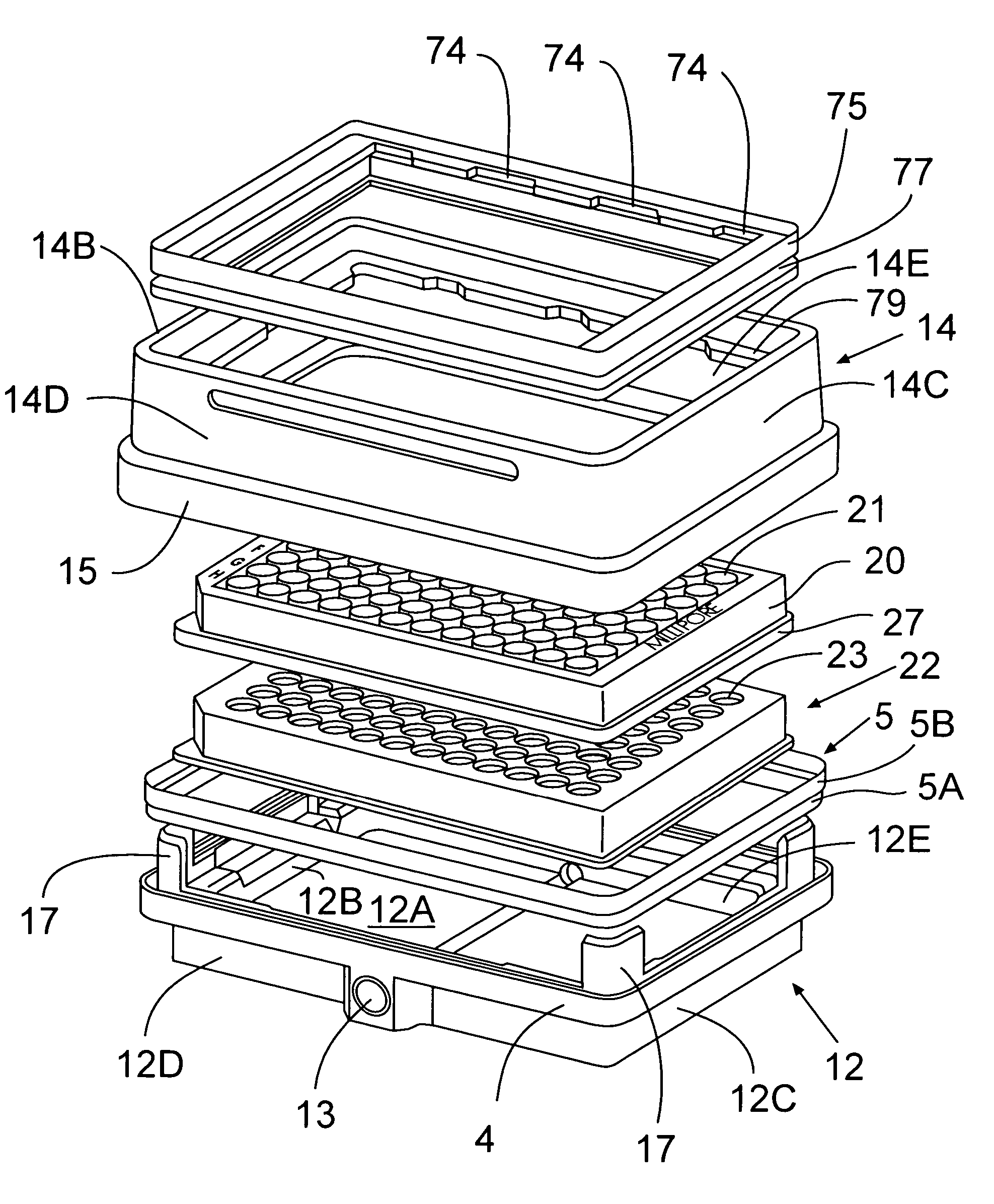
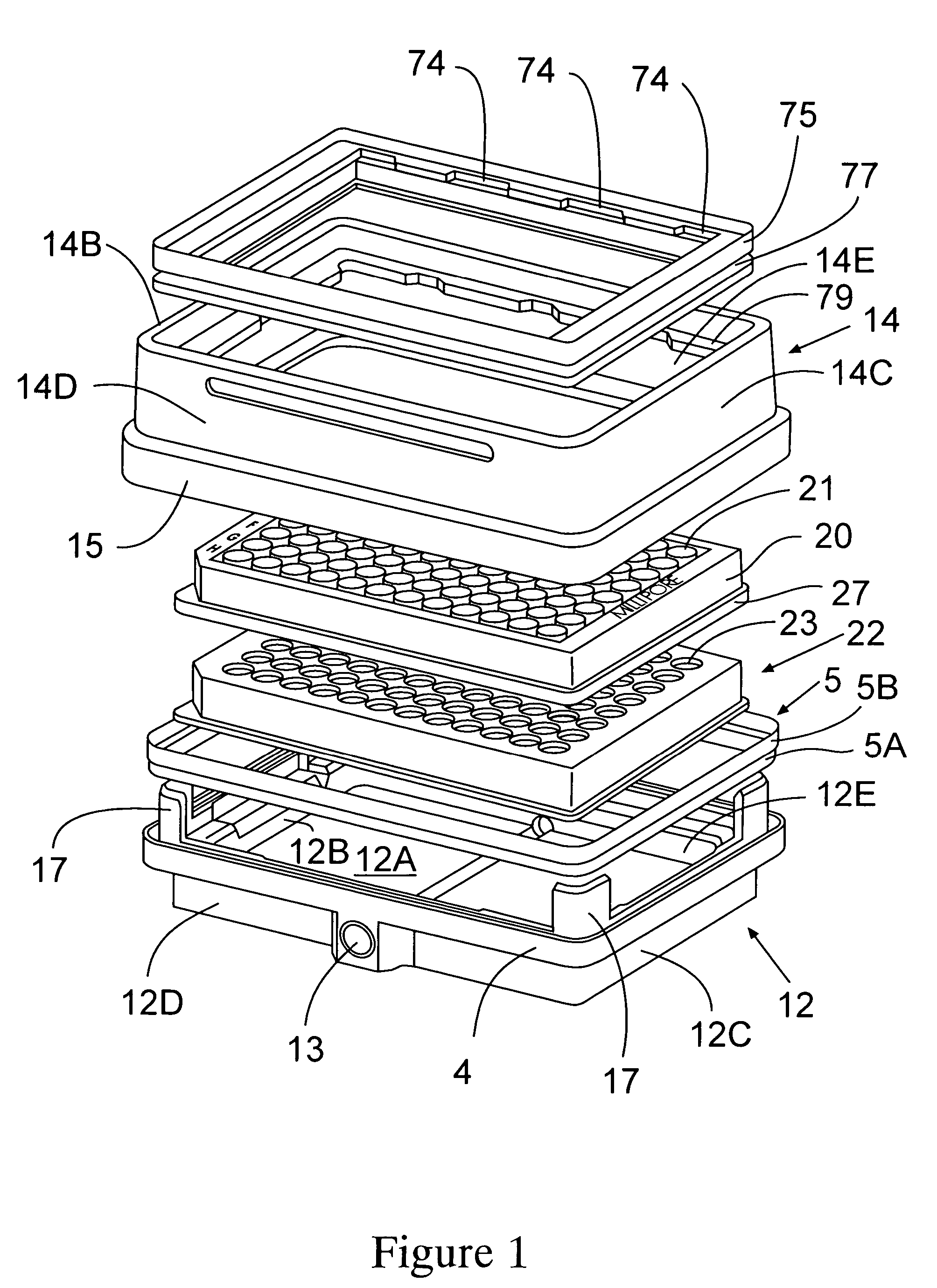
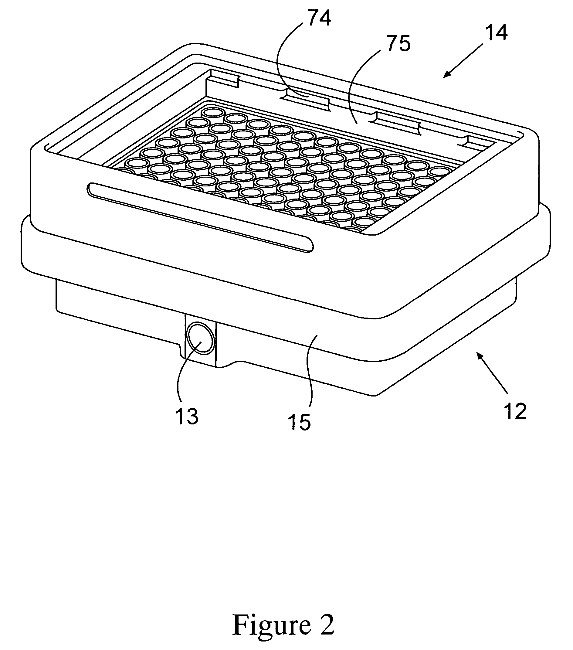
[0034]There are two common components in the vacuum manifold assembly in accordance with the present invention, regardless of the application. With reference to FIG. 1, the common components are a base 12 and a collar 14, together sized and configured to contain sample-processing components. The base 12 optionally includes a port 13 for communication with a driving force, such as a source of vacuum, preferably a vacuum pump. Alternatively, the port 13 maybe located in a wall of the collar as shown in FIG. 14. The base 12 also includes a bottom 12A and one or more sidewalls upstanding therefrom. In the rectangular embodiment shown, there are four connecting sidewalls, namely, opposite sidewalls 12B and 12C, and opposite sidewalls 12D and 12E. The base includes an outer peripheral flange 4 that in combination with an inner peripheral portion of the sidewalls forms a peripheral groove 6 (FIG. 8) that receives gasket 5. Preferably the gasket 5 has a lower peripheral portion 5A that seat...


PUM

PropertyMeasurementUnit
volumeaaaaaaaaaa
elution volumesaaaaaaaaaa

Abstract

A laboratory device design particularly for a multiplate format that includes a manifold wherein the position of the plate is not a function of gasket compression or vacuum rate applied. In one embodiment, the device has a modular design, wherein one or more removable inserts, preferably with different functionalities can be positioned between a base component and a collar component. The particular insert(s) chosen depend on the desired sample preparation or assay to be carried out. The insert(s) are stacked and are positioned between the base and collar as a unit, so that the stack within the manifold does not move during evacuation of the vacuum chamber. The consistent position of the insert(s) facilitates using vacuum sample processing with automated liquid handlers.

Description

BACKGROUND OF THE INVENTION[0001]Test plates for chemical or biochemical analyses, which contain a plurality of individual wells or reaction chambers, are well-known laboratory tools. Such devices have been employed for a broad variety of purposes and assays, and are illustrated in U.S. Pat. Nos. 4,734,192 and 5,009,780, for example. Microporous membrane filters and filtration devices containing the same have become particularly useful with many of the recently developed cell and tissue culture techniques and assays, especially in the fields of bacteriology and immunology. Multiwell plates, used in assays, often utilize a vacuum applied to the underside of the membrane as the driving force to generate fluid flow through the membrane.[0002]The microplate has been used as a convenient format for plate processing such as pipetting, washing, shaking, detecting, storing, etc. A variety of assays have been successfully formatted using multiwell filter plates with vacuum driven follow-thro...

Claims


Application Information

Patent Timeline
Patent Type & Authority Patents(United States)
IPC IPC(8): B01L3/02B01D29/50G01N1/10B01D61/14B01D61/18B01D61/58B01L3/00
CPCB01D61/18B01L3/50255B01L2200/023B01L2200/025Y10T436/255B01L2300/0829B01L2400/049Y10T436/2575Y10T436/25375B01L2200/141
Inventor CLARK, PHILLIPGREENIZEN, KURT E.DOYLE, JOHN
Owner MILLIPORE CORP
Why Eureka
Try Eureka