
Supercharger control system

a control system and supercharger technology, applied in the direction of interengaging clutches, gearing, hoisting equipment, etc., can solve the problems of increased fuel consumption, reduced engine efficiency, and engine work harder, so as to reduce engine exhaust emissions, high-speed engine performance, and increase fuel efficiency

Inactive Publication Date: 2009-09-22
MACHNER BILLY
View PDF28 Cites 9 Cited by
  • Summary
  • Abstract
  • Description
  • Claims
  • Application Information

AI Technical Summary

Benefits of technology

"The present invention is a supercharger control system that can be easily installed on the existing crankshaft of a vehicle engine to control the operation of the vehicle's supercharger. It is a compact, solid mount unit that allows the driver to easily switch the supercharger on and off. It also helps keep the supercharger cooler, reducing wear and tear on the engine and improving fuel efficiency. The system can be retrofitted into aftermarket vehicles with superchargers or offered as standard or optional equipment with new production vehicles. It can also be converted to a single pulley system for increased power in the racing mode. The invention is designed to overcome the limitations and disadvantages of prior supercharger control systems."

Problems solved by technology

However, most superchargers are driven by the engine itself and, as a result, when the supercharger is operational, the engine must work harder.
This causes a reduction in engine efficiency, more fuel is consumed, and there are more emissions.
There is also increased wear and tear on engine components.
These factors have kept superchargers off many vehicles and, for motorists who still have superchargers in use on their engines, caused them added expense for fuel and parts.
However, these prior attempts have been shown to be inefficient or problematic in actual operation.
Many also involve complex mechanisms which must be integrally incorporated into the vehicle engine.

Method used


Image

  • Supercharger control system
  • Supercharger control system
  • Supercharger control system

Examples


Embodiment Construction

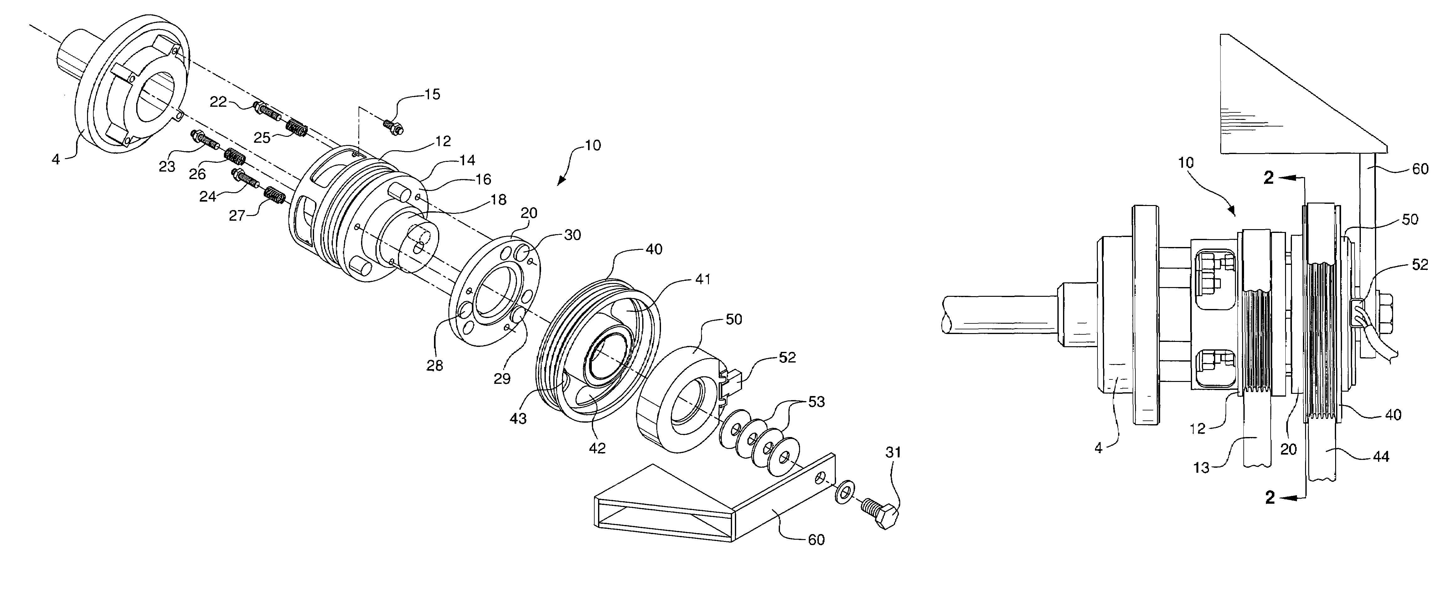
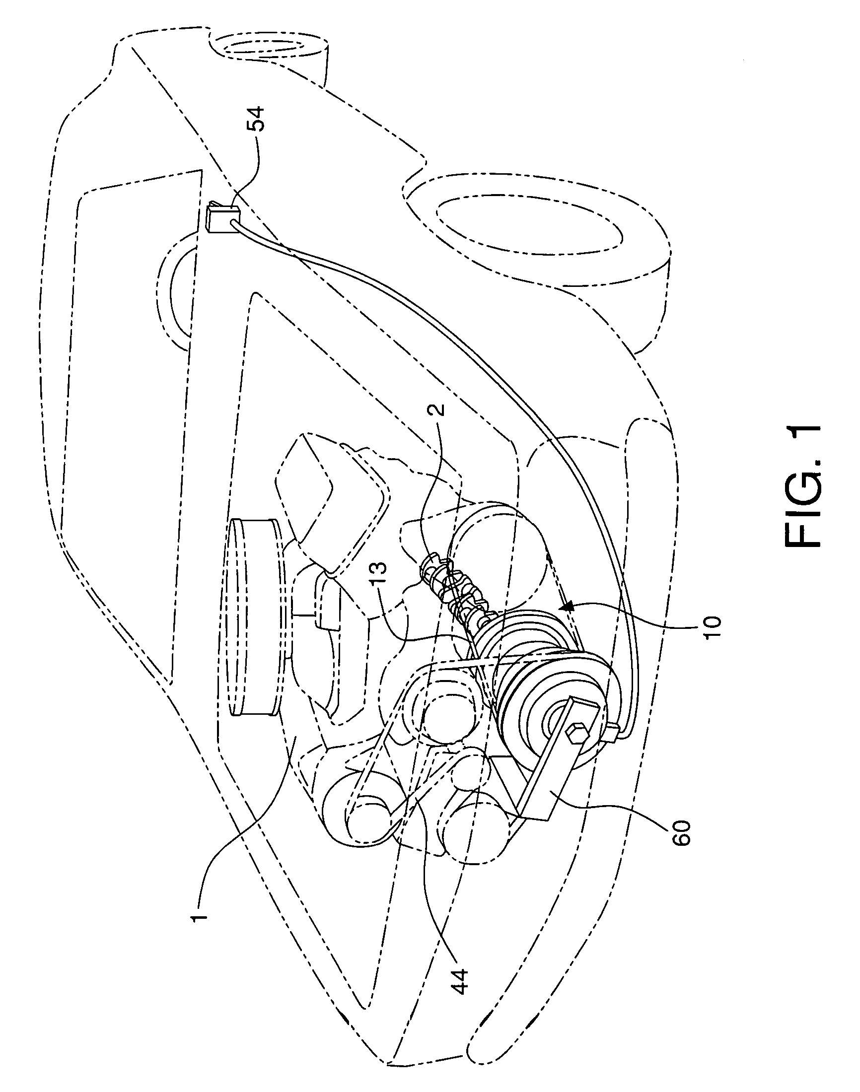
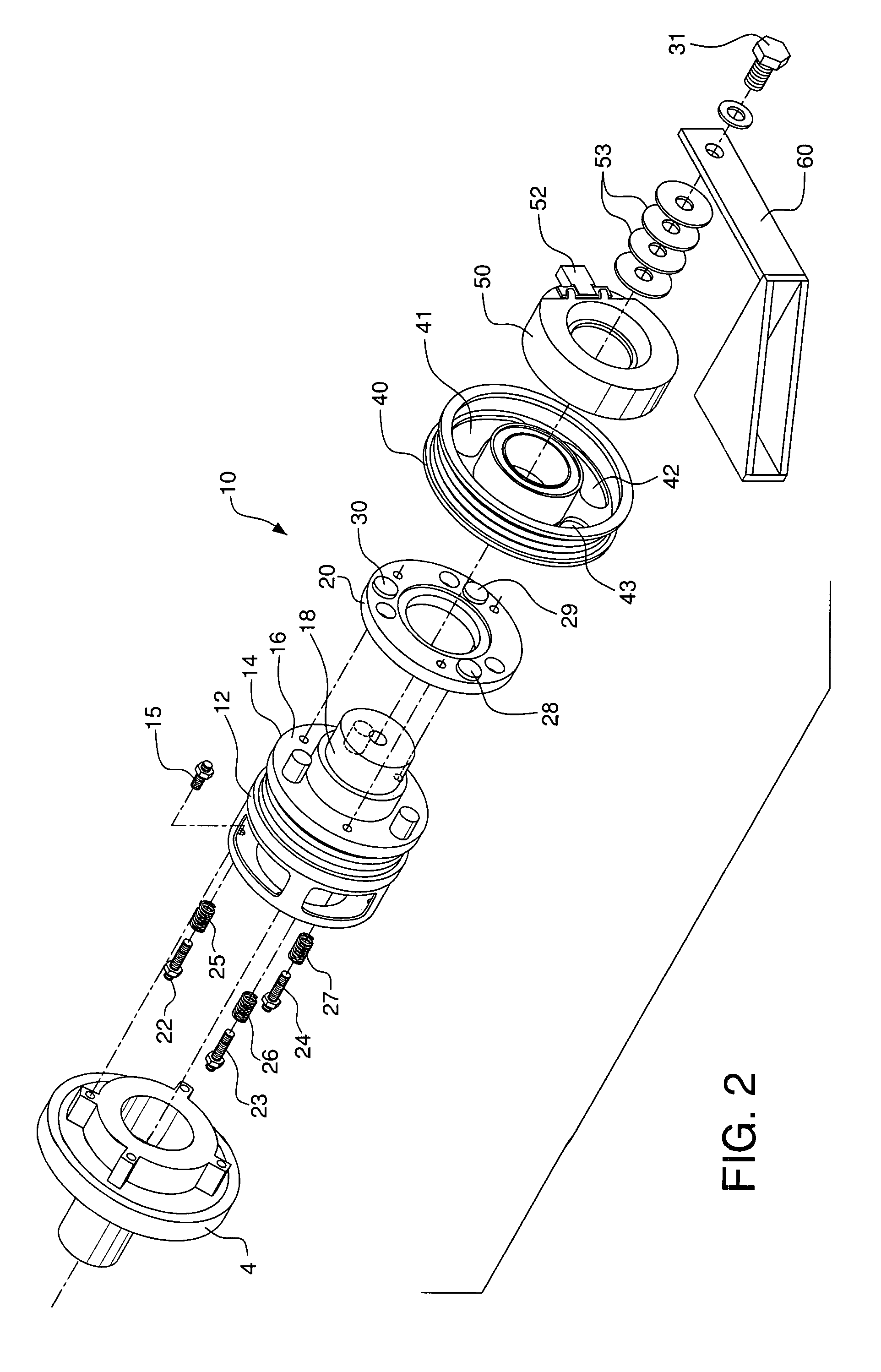
[0021]Vehicle engine 1 comprises a standard crankshaft 2 connected at the bottom front of the engine to a common harmonic balancer unit 4 (not shown in FIG. 1). The other end of harmonic balancer 4 in turn is connected to the supercharger control system 10 of the present invention. Control system 10 comprises accessory crank pulley 12 which is connected, by bolts 15, to balancer 4. Power from engine 1 is transmitted from crankshaft 2, through balancer 4 to rotate accessory pulley 12. Belt 13 around accessory pulley 12 in turn rotates to operate the vehicle accessories. Accessory pulley 2 and its belt 13 are configured to rotate continuously while the engine is running.

[0022]Shaft element 14, which comprises connection plate 16 and shaft 18, is connected to the outboard end of accessory pulley 12. Shaft 18 is configured to be free spinning within accessory pulley 12. Interconnection means in the form of slide plate 20 is aligned substantially parallel to accessory pulley 12 and shaft...


PUM


Abstract

A supercharger control system is installed at the bottom front end of the engine, directly onto the crankshaft. An accessory drive belt around the accessory belt pulley rotates continuously to keep vehicle accessories operating. A second belt around a larger pulley drives the supercharger blower. When the dashboard mounted switch is turned on, electricity from the engine energizes an electromagnet, which compels engagement of the rotating accessory pulley with the supercharger pulley by means of a slide plate. The belt around the supercharger pulley then rotates, operating the supercharger. If the driver does not require extra power and performance delivered by the supercharger, the switch is turned off, stopping the flow of electricity. This shuts down the magnetic field, causing the pulleys to be disengaged and disconnecting the supercharger, while still allowing the crankshaft to operate the accessories.

Description

BACKGROUND OF THE INVENTION[0001]A supercharger is commonly installed on a vehicle internal combustion engine to provide air at high pressure into the engine's intake manifolds. The primary purpose of this added, high pressure air is to increase engine power output, i.e. engine horsepower. However, most superchargers are driven by the engine itself and, as a result, when the supercharger is operational, the engine must work harder. This causes a reduction in engine efficiency, more fuel is consumed, and there are more emissions. There is also increased wear and tear on engine components. These factors have kept superchargers off many vehicles and, for motorists who still have superchargers in use on their engines, caused them added expense for fuel and parts.[0002]To address these problems, when an internal combustion engine is provided with a mechanical supercharging system, the supercharger blower is attached to the engine crankshaft by a supercharger clutch assembly. When the eng...

Claims


Application Information

Patent Timeline
Patent Type & Authority Patents(United States)
IPC IPC(8): F02B33/00F16D11/06F16D19/00F16D21/02F16F15/30F16H33/00F16H7/00F16H9/00F16H9/16
CPCF02B33/34F02B39/04F02B39/12Y10T74/2127Y10T74/18344
Inventor MACHNER, BILLY
Owner MACHNER BILLY
Learn More