Process for manufacturing a cable resistant to external chemical agents

a technology of chemical agents and manufacturing processes, applied in the manufacture of power cables, cable/conductor materials, plastic/resin/waxes insulators, etc., can solve the problems of compromising the overall lifetime performance of the cable, mechanical properties, and the increase of the weight of the sheath, so as to achieve the effect of effective sealing and greatly improve the coupling between the coated metal tape and the polyamide layer

Active Publication Date: 2009-10-13
PRYSMIAN CAVI E SISTEMI ENERGIA
View PDF17 Cites 15 Cited by
  • Summary
  • Abstract
  • Description
  • Claims
  • Application Information

AI Technical Summary

Benefits of technology

[0021]The Applicant has now found that a cable with an effective seal against the penetration of both humidity and chemical agents can be obtained by folding an ethylene-based adhesive coated metal tape around the cable insulation, with overlapping edges, and extruding a polyamide coating layer directly around said folded aluminum tape. In particular, the Applicant has found that the coupling between the coated metal tape and the polyamide layer is greatly improved by carrying out the extrusion in certain conditions. More in particular, the Applicant has found that the extrusion of said polyamide coating layer has to be carried out controlling the draw down ratio (DDR).
[0022]Moreover, the Applicant has also found that, thanks to the use of said ethylene-based adhesive coated metal tape and said polyamide coating layer and to the effective protection against both humidity and chemical agents so obtained, it is possible to provide an effective mechanical protection to the cable by means of a protecting coating layer made of an expanded polymeric material. Said protecting coating layer made of an expanded polymeric material would be otherwise degraded by the penetration of both humidity and chemical agents. In this way, the metal armour usually applied to the cables commercially available in order to protect them from possible damages caused by accidental impacts, may be avoided.
[0023]In particular, the Applicant has found that by inserting into the structure of a cable, in a radially inner position with respect to the metal tape, a protecting coating layer made of an expanded polymeric material having adequate thickness and flexural modulus it is possible to obtain a cable having high impact strength, thereby making it possible to avoid the use of said protective metal armour. A cable with a protecting coating layer of this type has various advantages over a commercial cable with a protective metal armour such as, for example, easier manufacturing process, reduction in weight and dimensions of the finished cable and a reduced environmental impact as regards recycling of the cable once its working cycle is over.
[0104]Cable coating layers with semiconductive properties may be produced in accordance with the known art and comprises, advantageously, a semiconductive polymeric material. Preferably, said polymeric material is of the same type as that used for the coating layer with electrical insulation properties, so as to ensure good adhesion and hence avoid detachments that would generate partial discharges and, ultimately, perforation of the cable.

Problems solved by technology

It is known that, in cables installed in critical environments such as, for example, oil refineries, oil pools, offshore installations, a major problem is given by the permeability of said polymeric cable coating layers to humidity and, in particular, to aggressive chemicals both of organic type such as, for example, hydrocarbons and solvents, and of inorganic type such as, for example, acids and bases.
Penetration of said elements to the interior of the cables compromise their overall lifetime performance both in term of mechanical properties and electrical properties.
However, such sheaths still provide significant weight increase.
Applicant has observed that the use of a sheath made of a laminated metal tape coated with an ethylene-based adhesive coating layer and a polyamide coating layer as disclosed, for example, in U.S. Pat. No. 4,675,471 above cited, is not as effective as desired in protecting the cable from the external attacks of both humidity and chemical agents.
In particular, Applicant has observed that, when said laminated metal tape is longitudinally folded around an insulated conductor, in particular in the case the edges of said metal tape are overlapped, the risks of penetration of both humidity and chemical agents to the interior of the cable is very high due to the fact that the polyamide present at said overlapping edges does not allow an effective bonding of the overlapping edges.
Therefore, the Applicant has faced the problem of avoiding the use of said additional polyethylene coating layer.
However, the Applicant has observed that, while it is possible to obtain a good adhesion between a metal tape coated with an ethylene-based adhesive coating layer and a polyamide coating layer by means of a calendering process, the same adhesion was not obtained by means of an extrusion process.
In particular, the Applicant has observed that the extrusion of a polyamide coating layer onto a longitudinally folded metal tape coated with an ethylene-based adhesive coating layer did not allow an effective coupling between the coated metal tape and the polyamide coating layer.

Method used


Image

  • Process for manufacturing a cable resistant to external chemical agents
  • Process for manufacturing a cable resistant to external chemical agents
  • Process for manufacturing a cable resistant to external chemical agents

Examples


example 1

Cable Production

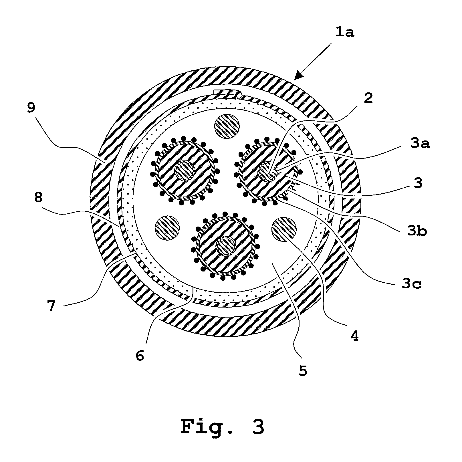
[0146]A medium-voltage cable of the tripolar type was prepared according to the construction scheme given in FIG. 3.

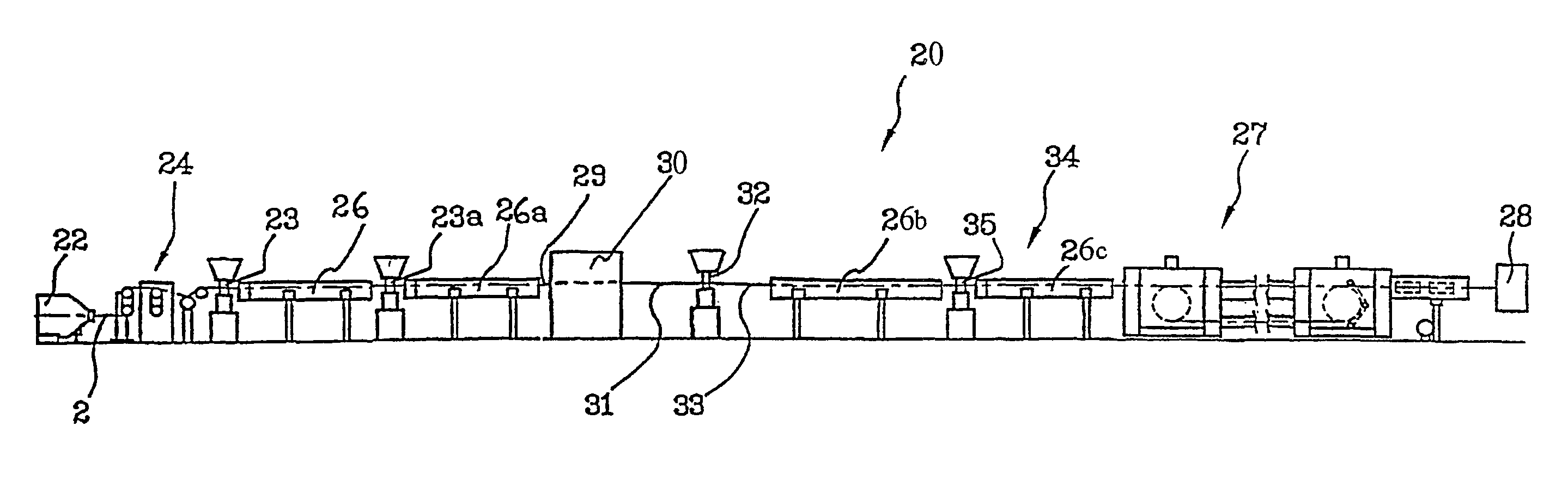
[0147]Each of the three cores possessed by said cable consisted of a copper conductor (of cross section equal to 150 mm2) coated on the extrusion line with a 0.8 mm thick internal semiconductive coating layer, a 5.5 mm thick insulating coating layer, a 0.5 mm thick external semiconductive coating layer, the three coating layers being made of a crosslinked ethylene / propylene rubber based compounds. The extrusion was carried out by means of a triple extrusion line which comprises: a 80 mm, 25 D single-screw extruder for the internal semiconductive coating layer, a 150 mm, 25D single-screw extruder for the insulating coating layer and a 90 mm, 25D single-screw extruder for the external semiconductive coating layer. The temperatures in the various zone of the extruders were, respectively, the following: 50-100-110-120-120° C., extrusion head 115° C.; 80-90-...

example 2

[0167]A cable was produced as disclosed in Example 1, the only difference being the fact that the continuous layer made of a polyamide 6 / linear low density polyethylene (LLDPE) blend (Orgalloy® LE 6000 from Atofina) was extruded at a draw down ratio (DDR) of 4.0.

Adhesion (Peeling) Test

[0168]Test pieces of the metal tape with the adhesive layer and the continuous coating layer with the following dimensions 10 mm width×100 mm length were obtained from the cable. Test pieces having the same dimensions were also obtained from the cable of Example 1.

[0169]Said pieces, were subjected to the peel test according to Standard EDF NF C 33-223 using an Instron 4202 dynamometer, the clamps of which were applied to the metal tape at one end and to the continuous coating layer at the other end (the two end were manually peeled off before applying the clamps). A traction speed equal to 50 mm / min was then applied and the peel force (PF) values thus measured, expressed in Newtons (N), are given below...


PUM

PropertyMeasurementUnit
temperatureaaaaaaaaaa
densityaaaaaaaaaa

Abstract

A process for manufacturing a cable includes the steps of conveying at least one conductor to an extruder apparatus; extruding an insulating coating layer radially external to the at least one conductor; longitudinally folding a metal tape around the extruded insulating coating layer, the metal tape bearing at least one adhesive coating layer in a radially external position; and extruding at least one continuous coating layer of at least one polyamide or a copolymer thereof around and in contact with the folded metal tape. The step of extruding the at least continuous coating layer is carried out at a draw down ratio not higher than 2.5, preferably, 1.2 to 2.0.

Description

CROSS REFERENCE TO RELATED APPLICATION[0001]This application is a national phase application based on PCT / US2004 / 011259, filed Apr. 27, 2004.BACKGROUND OF THE INVENTION[0002]1.Field of the Invention[0003]The present invention relates to a process for manufacturing a cable resistant to external chemical agents.[0004]More particularly, the present invention relates to a process for manufacturing a cable, in particular an electrical cable for low-voltage, medium-voltage or high-voltage power transmission and / or distribution, which comprises at least one conductor, at least one metallic tape coated with at least one adhesive coating layer and at least one coating layer comprising at least one polyamide or a copolymer thereof.[0005]2. Description of the Related Art[0006]Within the scope of the present invention, “low-voltage” generally means a voltage up to 1 kV, “medium-voltage” means a voltage between 1 kV and 35 kV, “high-voltage” means a voltage greater than 35 kV.[0007]Electrical ca...

Claims


Application Information

Patent Timeline
Patent Type & Authority Patents(United States)
IPC IPC(8): H01B7/18H01B3/30H01B7/28H01B9/02H01B13/14H01B13/26
CPCH01B3/30H01B13/14H01B7/2813
Inventor LUMACHI, ALBERTOVEGGETTI, PAOLODE RAI, LUCA GIORGIOO'NEIL, FRANCKBAREGGI, ALBERTOFRIGERIO, MARCOBELLI, SERGIO
Owner PRYSMIAN CAVI E SISTEMI ENERGIA
Why Eureka
Try Eureka