Filter device

a filter device and filter technology, applied in the direction of overvoltage protection resistors, emergency protective arrangements for limiting excess voltage/current, arrangements responsive to excess voltage, etc., can solve the problem of high-speed switching in power semiconductor devices, motors generate electric corrosion in bearings, and high-frequency leakage current, etc. problems, to achieve the effect of simple configuration, effective suppression of electromagnetic interferen

Active Publication Date: 2009-10-20
TOYO DENKI SEIZO KK
View PDF21 Cites 39 Cited by
  • Summary
  • Abstract
  • Description
  • Claims
  • Application Information

AI Technical Summary

Benefits of technology

[0014]An alternating current motor is used as an example of an alternating current circuit. When a common mode voltage applied to input terminals of the alternating current motor is set to zero, a shaft voltage of the alternate motor becomes zero, and a leak current (ground line current) also becomes zero. The present invention is based on the idea that a shaft voltage and a leak current are set near to zero by setting the common mode voltage applied to these input terminals to as close to zero as possible, thereby suppressing the electromagnetic interference. Based on the configuration according to the present invention explained below, it becomes possible to bring the common mode voltage applied to the input terminals of the alternating current motor (the alternating current circuit) close to zero.
[0018]In order to achieve the above object, as a modification of the first aspect of the present invention, there is provided a filter device that suppresses electromagnetic interference generated in an alternating current circuit connected to a power converter with an alternating current input and an alternating current output. In the filter device, a common mode choke is connected to an alternating current input terminal side of a power converter with an alternating current input and an alternating current output. At the same time, an outgoing line from the neutral point of the alternating current circuit is connected to a power source system side of the common mode choke, that is, a reference potential point having little potential variation present at the upstream of the common mode choke, preferably via a passive element including a capacitor and a resistor connected in series.
[0019]In order to achieve the above object, according to a second aspect of the present invention, there is provided a filter device that suppresses electromagnetic interference generated in an alternating current circuit connected to a power converter with an alternating current input and an alternating current output. In the filter device, a common mode choke is provided at a direct current input terminal side of a power converter with a direct current input and an alternating current output connected to input terminals of the alternating current circuit. At the same time, an outgoing line from the neutral point of the alternating current circuit is connected to a direct current power source side of the common mode choke, that is, a reference potential point having little potential variation present at the upstream of the common mode choke, preferably via a passive element including a capacitor and a resistor connected in series.
[0020]In order to achieve the above object, as a modification of the second aspect of the present invention, there is provided a filter device that suppresses electromagnetic interference generated in an alternating current circuit connected to a power converter system including a power converter with an alternating current input and a direct current output and a power converter with a direct current input and an alternating current output. In this filter device, a common mode choke is connected to between direct current output terminals of the power converter with the alternating current input and the direct current output and direct current input terminals of the power converter with the direct current input and the alternating current output. At the same time, an outgoing line from the neutral point of the alternating current circuit is connected to a reference potential point having little potential variation at an alternating current input terminal side or the direct current output terminal side of the power converter with the alternating current input and the direct current output, preferably via a passive element including a capacitor and a resistor connected in series.
[0021]According to the present invention, the filter device has a common mode choke, and has a closed loop formed from the neutral point of the alternating current circuit to the reference potential point at the power source system side of the power converter. Based on this simple configuration, electromagnetic interference (EMI) can be effectively suppressed. Particularly, unlike the conventional example, the filter device according to the present invention does not require constituent elements such as a normal mode choke and transistors, and has a simple configuration. As a result, the filter device can be compact and can be provided at low cost.

Problems solved by technology

On the other hand, electromagnetic interference (EMI) attributable to high-speed switching in a power semiconductor device is becoming a crucial issue in the our highly information-oriented and computerized society.
The resultant high-frequency leakage current that flows through parasitic capacitors of the motor generates electric corrosion in the bearings.
This can cause problems in the rotation of the motor and has the potential of being a large noise source in the power line Internet, in which PCs communicate with other devices through the power line, which will come into practical use in the future.
According to the above conventional techniques, there has been provided a certain effect of suppressing the EMI, but at an insufficient level.
Further, due to the limit of a withstand voltage of obtainable transistors, this EMI filter can be applied to only to a 200 volt or less inverter.
The EMI also has a complex structure and, accordingly, has a high manufacturing cost.
However, because a normal mode choke is necessary, the device becomes large and has a high manufacturing cost.

Method used


Image

  • Filter device
  • Filter device
  • Filter device

Examples


first embodiment

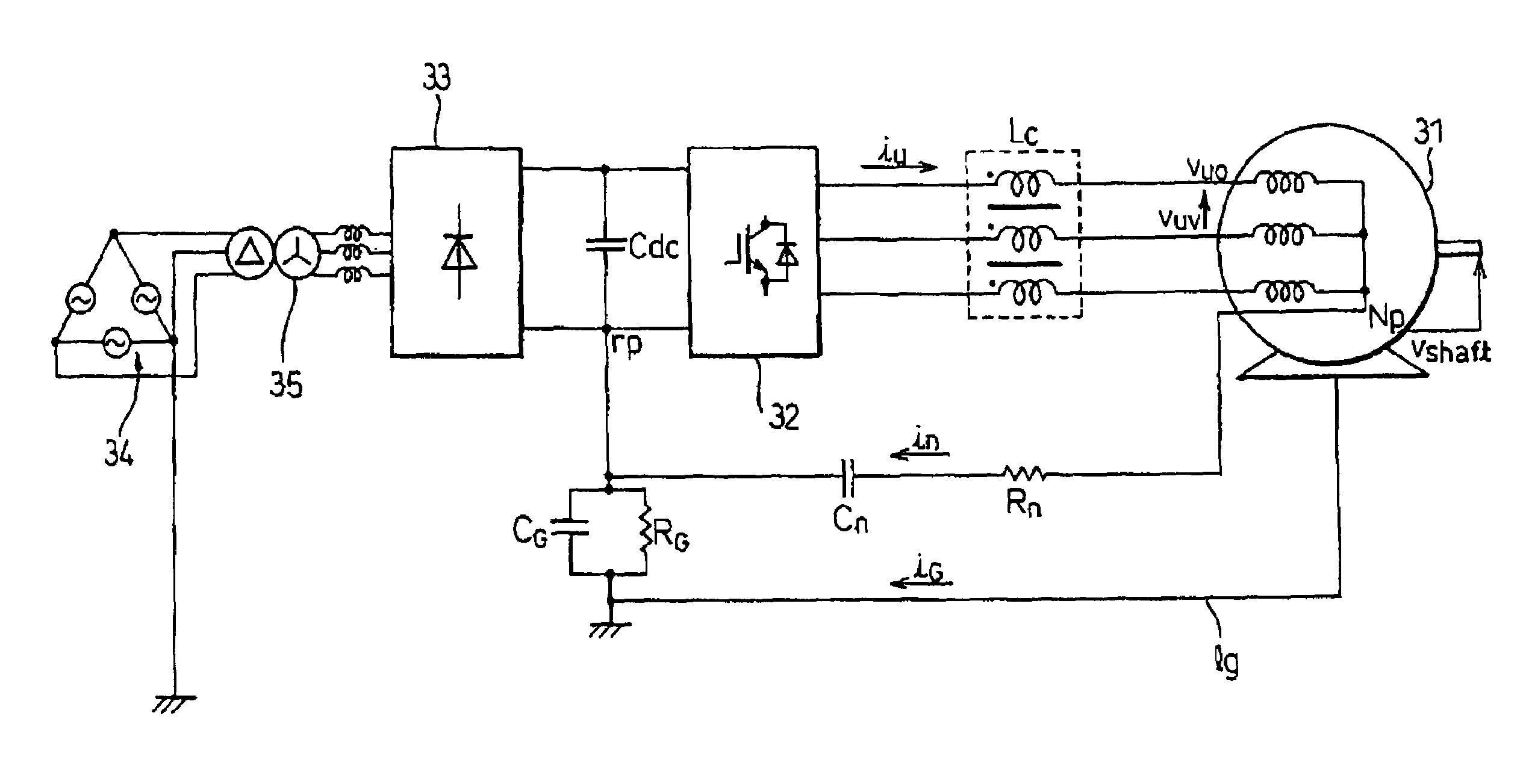
[0057]FIG. 3 is a circuit diagram of a filter device according to the present invention.

[0058]The present embodiment corresponds to the embodiment in the first aspect of the present invention. The alternate circuit is a three-phase induction motor 31. The power converter with the alternating current output is an inverter 32. The induction motor 31 is inverter driven by the inverter 32. In FIG. 3, a ground line lg of a frame of the induction motor 31 is also shown.

[0059]In order to ground the minus terminals at the direct current input side of the inverter 32, a capacitor CG and a resistor RG that are connected in parallel are provided. The capacitor CG operates as a capacitor grounding for a high frequency component, and the resistor RG operates as a resistor grounding for a low frequency component.

[0060]A direct current capacitor Cdc is provided to store power at the power source system side of the inverter 32.

[0061]The inverter 32 is connected to a diode rectifier 33 that rectifie...

second embodiment

[0084]A filter device according to the present invention is explained next.

[0085]FIG. 6 is a circuit diagram of the filter device according to the second embodiment of the present invention. FIG. 7 is an equivalent circuit diagram of the filter device according to the second embodiment of the present invention, and shows an equivalent circuit in a carrier frequency area in a common mode shown in FIG. 6.

[0086]The present embodiment corresponds to the embodiment according to the first aspect of the present invention. In the first embodiment shown in FIG. 3, a normal mode filter configured by a parallel circuit of a normal mode choke (that is, an alternating current reactor) L and a resistor R is further connected in series between the inverter 32 and the common mode reactor, with a view to decreasing resonance in a megahertz area. Other circuit configurations are similar to those of the first embodiment.

[0087]Based on the same idea of the equivalent circuit explained in the first embo...

third embodiment

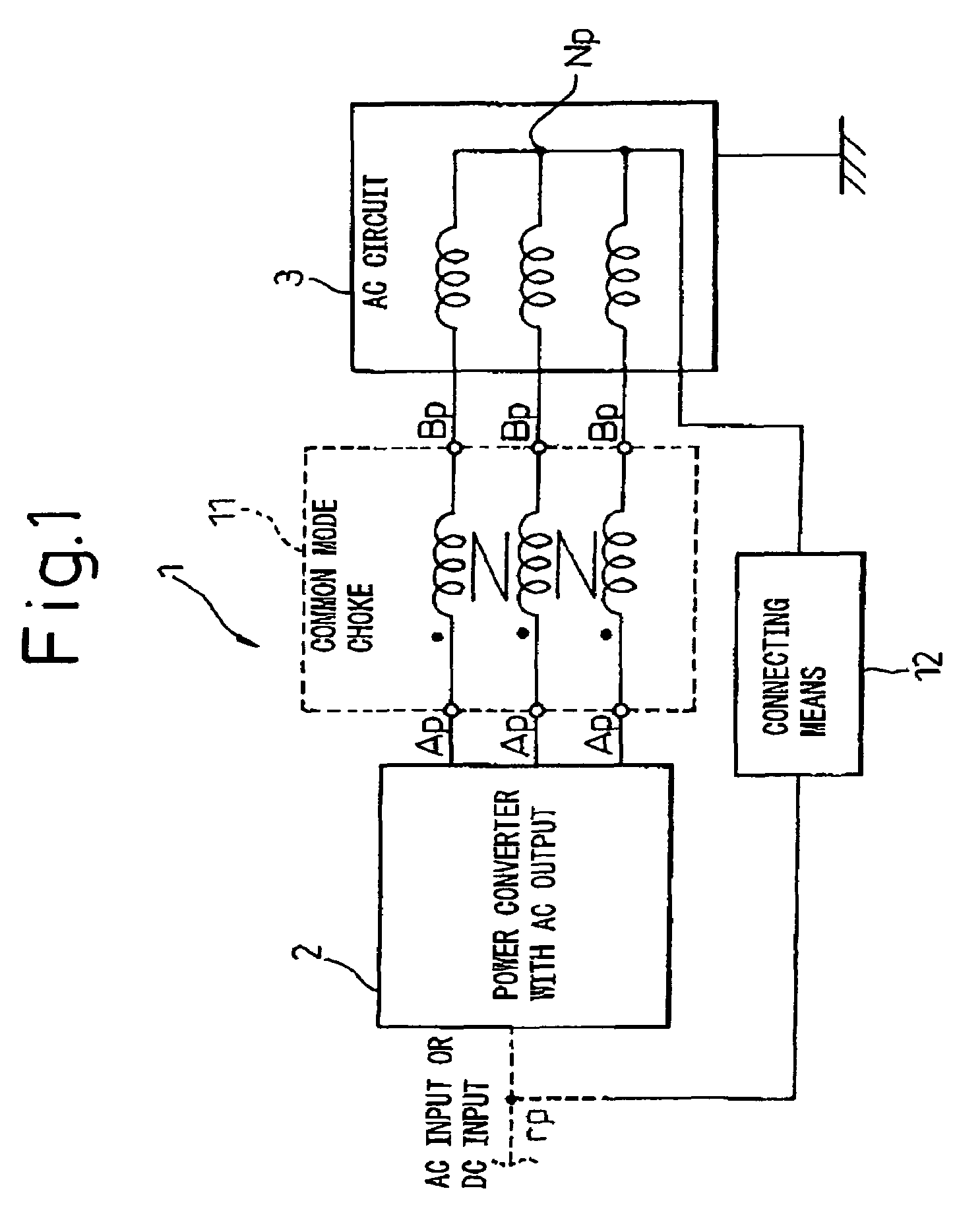
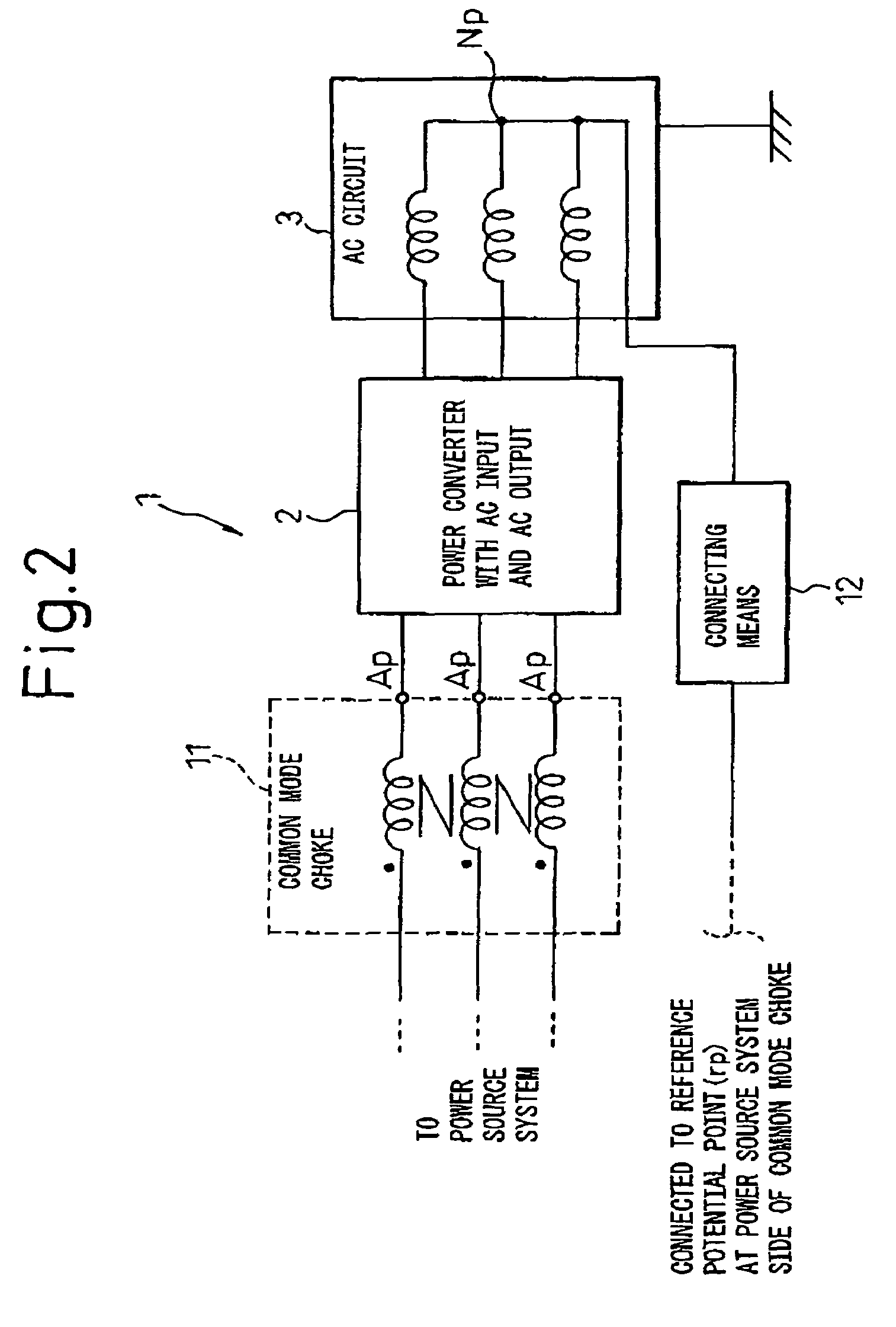
[0089]Next, a filter device that is applied when the power converter explained with reference to FIG. 1 is a converter with an alternating current input and an alternating current output is explained as the present invention.

[0090]FIG. 8 is a circuit diagram (part 1) of a filter device according to the third embodiment of the present invention, where a point having little voltage variation that becomes a reference potential point is not present at the input side of the power converter. FIG. 9 is a circuit diagram (part 2) of a filter device according to the third embodiment of the present invention, where a point having little voltage variation that becomes a reference potential point is present at the input side of the power converter.

[0091]The present embodiment corresponds to the embodiment according to the first aspect of the present invention. In the filter device 1, the power converter 2 shown in FIG. 8 and FIG. 9 is used as the converter with an alternating current input and ...


PUM


Abstract

A filter device that suppresses electromagnetic interference generated in an alternating current circuit connected to a power converter with an alternating current output includes: a common mode choke connected to between any one terminal at an input side, an output side, or a direct current link of the power converter and input terminals of the alternating current circuit; and a connecting element that connects an outgoing line from a neutral point of the alternating current circuit to a reference potential point having little potential variation at an upstream of the common mode choke.

Description

RELATED APPLICATIONS[0001]The present application is based on International Application No. PCT / JP2003 / 003119, filed Mar. 14, 2003, and claims priority from, International Application Numbers PCT / JP2002 / 11742 and PCT / JP2002 / 11888, filed Nov. 11 and 14, 2002, respectively, the disclosures of which are hereby incorporated by reference herein in its entireties.TECHNICAL FIELD[0002]The present invention relates to a filter device that suppresses the occurrence of electromagnetic interference in an alternating current circuit that is connected to an alternating current output of a power converter.BACKGROUND ART[0003]Along with an increase in the switching speeds of power semiconductor devices such as IGBTs (insulated gate bipolar transistors), the torque control and speed control of an alternating current motor variable-speed drive system including these power semiconductor devices has become better, which makes a large contribution to energy savings in the total system.[0004]On the othe...

Claims


Application Information

Patent Timeline
Patent Type & Authority Patents(United States)
IPC IPC(8): H02M1/12H02M5/10H02M5/27H02M5/45
CPCH02M1/12H02M1/126H02M5/271H02M5/4505H02M5/10H02M2001/123H02M1/123
Inventor AKAGI, HIROFUMI
Owner TOYO DENKI SEIZO KK
Why Eureka
Try Eureka