Electrochemical micromanufacturing system and method

a micromanufacturing and electrochemical technology, applied in the field of electrochemical deposition, can solve the problems of reducing the efficiency of microelectronic systems, so as to achieve high electrical resistance and high deposition rate , the effect of easy dissolution or etching

Inactive Publication Date: 2009-11-10
UNIV OF WASHINGTON
View PDF6 Cites 54 Cited by
  • Summary
  • Abstract
  • Description
  • Claims
  • Application Information

AI Technical Summary

Problems solved by technology

The manufacture of microelectromechanical systems (“MEMS”) is currently impaired not by the microelectronic side of MEMS, but rather by the micromechanical side.
Some of these methods have been tailored to produce structures with significant thickness, for example, LIGA (lithography, electroplating, and molding), and thick UV photolithography for electrodeposition, bulk silicon micromachining, silicon direct bonding, etc., but the drawbacks are still present—namely, the reliance of mask sets and the associated labor when it comes to changing device design (which requires another mask set).
Additionally, the three-dimensional complexity attainable with such methods is limited; the number of layers rarely exceeding a few dozen.
The MEMS Exchange (www.memsnet.org) cites the two main challenges facing the microelectromechanical systems (“MEMS”) community as—(1) insufficient access to MEMS fabrication facilities; and (2) an entanglement of the MEMS design process with the inherent complexities of current fabrication methodologies.
Both of these issues stem from the following fact that conventional mask-based microelectronic fabrication processes are still the predominate means of MEMS prototyping.
These problems lie predominately on the micromechanical side of MEMS.
Tethering the process to lithographic masks, however, limits the number of layers that can feasibly be incorporated in the micromechanical structure, thus constraining design freedom and three-dimensionality.
Furthermore, the mask dependency typically requires that fabrication be conducted in a cleanroom facility, which represents a substantial cost to the designer.
Due to the limited materials available for most rapid prototyping processes, these tests are typically limited to form-fit testing.
The finished parts, however, can be fragile and porous.
Additionally, it may be difficult to remove the excess / nonbound powder from the cavities within the part.
This process suffers from disadvantages similar to those of 3D Printing, however, in that the resulting part is porous.
An additional complication, owing to the necessary heating of the powder, is the potential for thermal distortion of the part.
A disadvantage associated with all processes involving deposition of molten or uncured materials, however, is the build-up of residual thermal stresses, which can cause warping and delamination in the finished product.
This process has yet to sever all ties with masks, making it somewhat inflexible; however, its “instant masks” are far more flexible than ordinary lithographic masks.

Method used


Image

  • Electrochemical micromanufacturing system and method
  • Electrochemical micromanufacturing system and method
  • Electrochemical micromanufacturing system and method

Examples


Embodiment Construction

[0028]The present invention will now be described with reference to the figures, wherein like numbers indicate like parts.

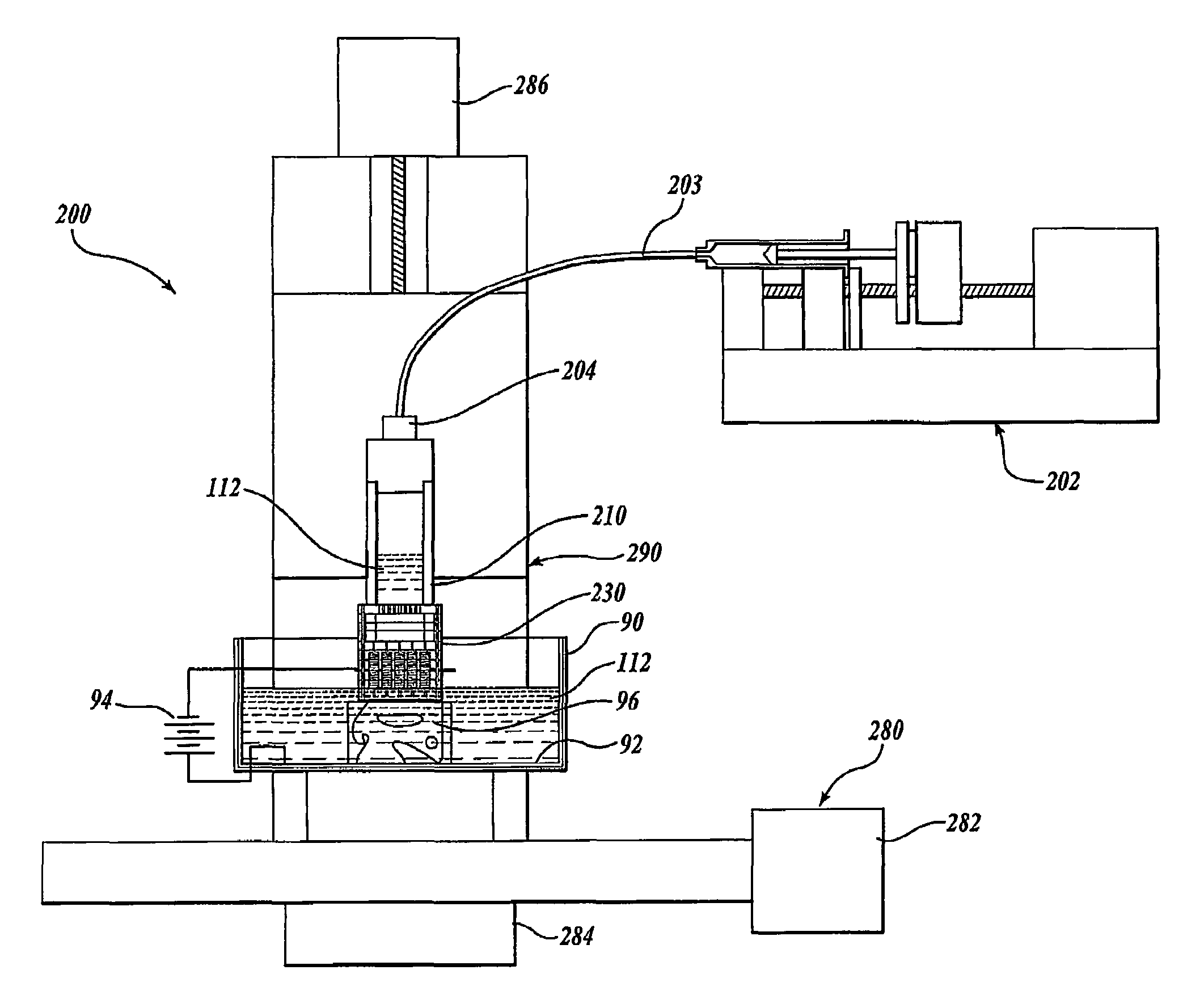
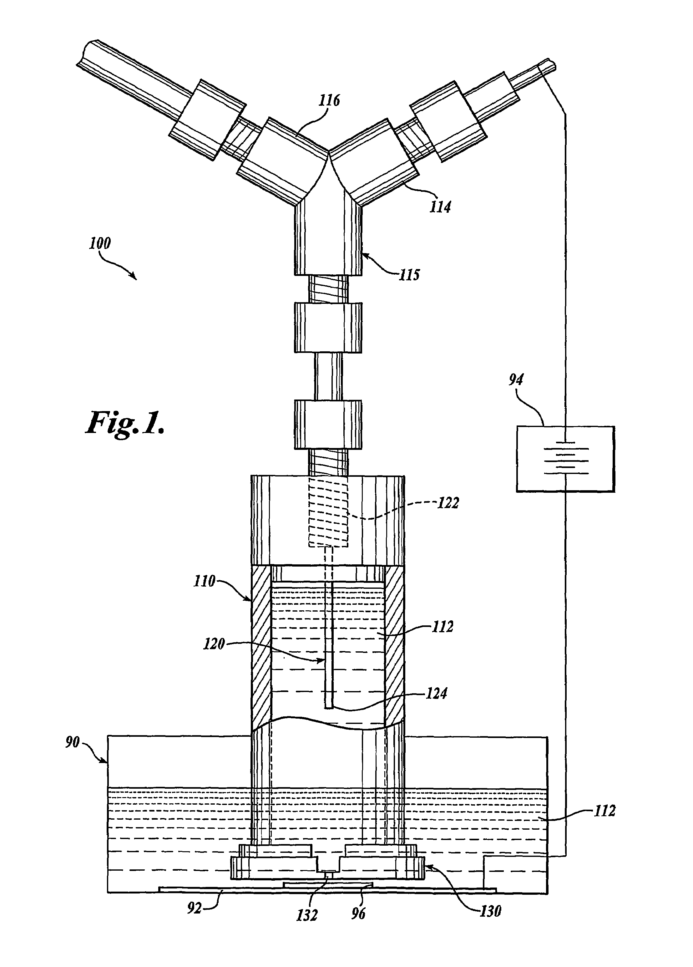
[0029]A single-pixel prototype embodiment of an electrochemical printing system 100 is shown in FIG. 1. The electrochemical printing system includes a head adapter 110 that is at least partially filled with an electrolyte 112. A counter electrode 120, for example, a platinum wire counter electrode, extends through a port opening 122 into the head adapter 110 and into the electrolyte 112. In the disclosed embodiment, the counter electrode 120 is threaded through one input port 114 of a Y-adapter 115, wherein a distal portion 124 of the counter electrode 120 is immersed in the electrolyte 112. The second input port 116 of the Y-adapter 115 is connected to a pressurized source of electrolyte 112, such that replenishing electrolyte is provided under pressure to the head adapter 110.

[0030]A printer head 130 is attached to the lower end of the head adapter 110. The pri...


PUM

PropertyMeasurementUnit
diameteraaaaaaaaaa
diameteraaaaaaaaaa
diametersaaaaaaaaaa

Abstract

An electrochemical printing system (100, 200) and method are disclosed having a printer head (130, 230) that expels a small jet of electrolyte (112) towards a conductive substrate (92) to facilitate electrodeposition or removal of material from the substrate. In an embodiment of the invention the printer head includes a plurality of individually addressable electrodes (220), each electrode having a channel therethrough and wherein the electrodes are much larger than the electrolyte jet outlet. The printer head includes means for inhibiting cross talk between electrodes. For example, the printer head may include a plenum (241) and a nonconductive cross-talk inhibition layer (245) upstream of the electrodes. A resolution defining layer (270) having small apertures (271) is provided at the distal end of the printer head.

Description

CROSS-REFERENCE TO RELATED APPLICATION[0001]This application claims the benefit of U.S. Provisional Patent Application No. 60 / 508,756, filed on Oct. 3, 2003, the disclosure of which is hereby expressly incorporated by reference, and priority from the filing date of which is hereby claimed under 35 U.S.C. § 120.STATEMENT OF GOVERNMENT LICENSE RIGHTS[0002]The invention was made with government support under Grant No. DMII-9978577 awarded by the National Science Foundation. The government has certain rights in the invention.FIELD OF THE INVENTION[0003]The present invention relates to electrochemical deposition and, more particularly, to the use of electrochemical deposition for micromanufacturing.BACKGROUND OF THE INVENTION[0004]The manufacture of microelectromechanical systems (“MEMS”) is currently impaired not by the microelectronic side of MEMS, but rather by the micromechanical side. Microelectronics is now a mature art—and primarily a two-dimensional one. Micro-mechanics, however,...

Claims


Application Information

Patent Timeline
Patent Type & Authority Patents(United States)
IPC IPC(8): C25D5/02C25D17/12G03FH05K3/22H05K3/24
CPCC25D5/02C25D5/026C25D5/08C25D17/12C25D1/00H05K3/241C25D1/003H05K2203/013H05K3/225B33Y10/00B33Y30/00
Inventor SCHWARTZ, DANIEL T.WHITAKER, JOHN D.
Owner UNIV OF WASHINGTON
Why Eureka
Try Eureka