Fast adapting filter

a filter and fast technology, applied in the field of gain control of signal filtering, can solve the problems that the gain circuit integrated with the filter may have a slow response time when the gain is changed, and achieve the effects of reducing direct current gain, simple and quick adaptation, and enhancing performan

Active Publication Date: 2009-11-10
NAT SEMICON CORP
View PDF8 Cites 6 Cited by
  • Summary
  • Abstract
  • Description
  • Claims
  • Application Information

AI Technical Summary

Benefits of technology

[0005]To address the above-discussed deficiencies of the prior art, it is a primary object of the present invention to provide, for use in a wireless receiver, adjustable gain circuits (AGCs) within serial filter stages that are initialized to maximum gain. The output of each AGC is then sampled and converted to digital representation for use by control logic in setting the gain for the respective AGC. The gain adjustment decision for each AGC is performed in one shot, sequentially backwards from the last AGC, such that gain may be adapted simply and quickly within a number of cycles equal to the number of AGCs. Performance is enhanced by a fast-adapting cell in which capacitances are switched into the input path and feedback loop of an amplifier to reduce direct current gain within the transfer function through charge sharing dividing down the output voltage.

Problems solved by technology

However, a gain circuit integrated with the filter may have a slow response time when the gain is changed.
The filter's bandwidth and the AGC settling time are typically the primary response time limitations for such circuits.

Method used


Image

  • Fast adapting filter
  • Fast adapting filter
  • Fast adapting filter

Examples


Embodiment Construction

[0014]FIGS. 1 through 5, discussed below, and the various embodiments used to describe the principles of the present invention in this patent document are by way of illustration only and should not be construed in any way to limit the scope of the invention. Those skilled in the art will understand that the principles of the present invention may be implemented in any suitably arranged device.

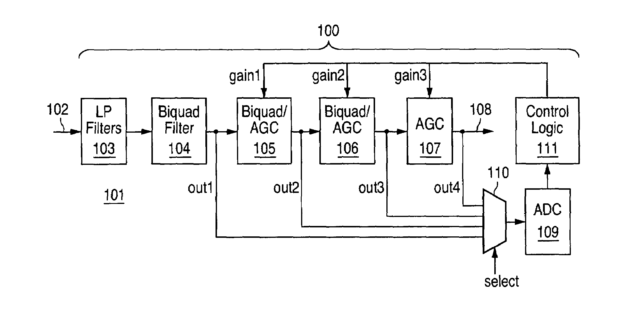
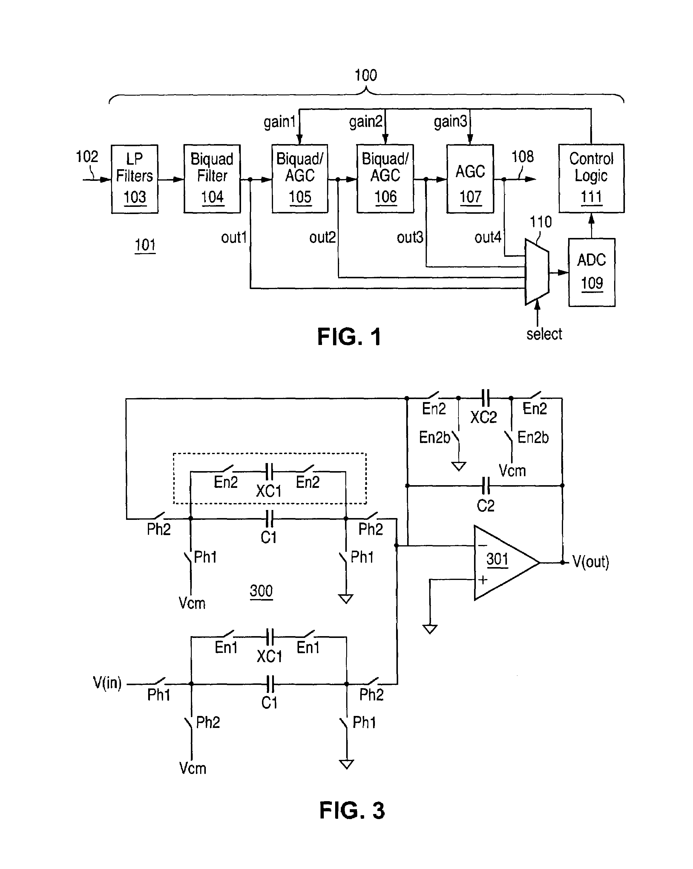
[0015]FIG. 1 depicts a fast adapting filter within a wireless device according to one embodiment of the present invention. The fast adapting filter system 100 of the present invention may be implemented within a wireless device 101 such as a mobile or cordless telephone, a personal digital assistant (PDA) with wireless communications capability, or a wireless connectivity device such as a wireless network interface for a laptop or other personal computer. The filter system 100 is implemented within the wireless receiver portion of a wireless device, and operates on a signal received by an anten...


PUM


Abstract

Adjustable gain circuits (AGCs) within serial filter stages are initialized to maximum gain. The output of each AGC is then sampled and converted to digital representation for use by control logic in setting the gain for the respective AGC. The gain adjustment decision for each AGC is performed in one shot, sequentially backwards from the last AGC, such that gain may be adapted simply and quickly within a number of cycles equal to the number of AGCs. Performance is enhanced by a fast-adapting cell in which capacitances are switched into the input path and feedback loop of an amplifier to reduce direct current gain within the transfer function through charge sharing dividing down the output voltage.

Description

TECHNICAL FIELD OF THE INVENTION[0001]The present invention is directed, in general, to wireless receivers and, more specifically, to gain control for signal filtering within wireless receivers.BACKGROUND OF THE INVENTION[0002]In wireless communication systems, the desired or wanted signals coexist with a wide band of unwanted signals, where the power of the unwanted signals can often be much higher than the power of the wanted signals.[0003]A filter is typically employed within wireless receivers to reject the unwanted signals. In addition, to optimize the system, an adjustable or adaptable gain circuit (AGC) associated with the filter is necessary to raise the power level of the wanted signal as early as possible within the receiver stages. However, a gain circuit integrated with the filter may have a slow response time when the gain is changed. The filter's bandwidth and the AGC settling time are typically the primary response time limitations for such circuits.[0004]There is, th...

Claims


Application Information

Patent Timeline
Patent Type & Authority Patents(United States)
IPC IPC(8): H03K5/00
CPCH03H21/0001
Inventor JU, SHU-INGWONG, HEE
Owner NAT SEMICON CORP
Why Eureka
Try Eureka