Supercharge Your Innovation With Domain-Expert AI Agents!

Retrograde well structure for a CMOS imager

a well structure and imager technology, applied in the field of silicon imaging devices, can solve the problems of high power dissipation of large arrays, ccd imagers also suffer from a number, and are susceptible to radiation damage, so as to improve signal-to-noise ratio, reduce cross talk, and improve quantum efficiency

Inactive Publication Date: 2009-11-17
APTINA IMAGING CORP
View PDF32 Cites 0 Cited by
  • Summary
  • Abstract
  • Description
  • Claims
  • Application Information

AI Technical Summary

Benefits of technology

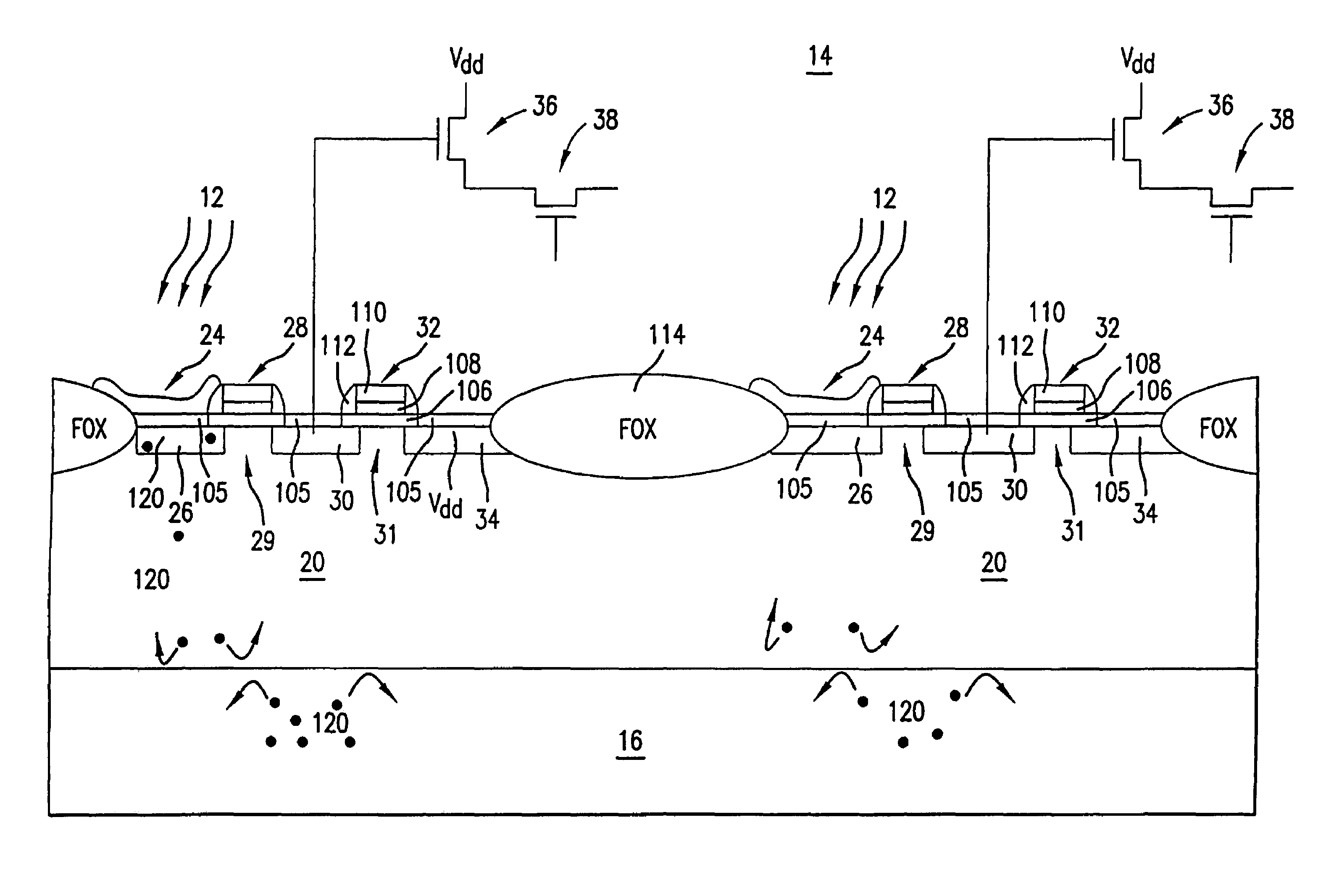
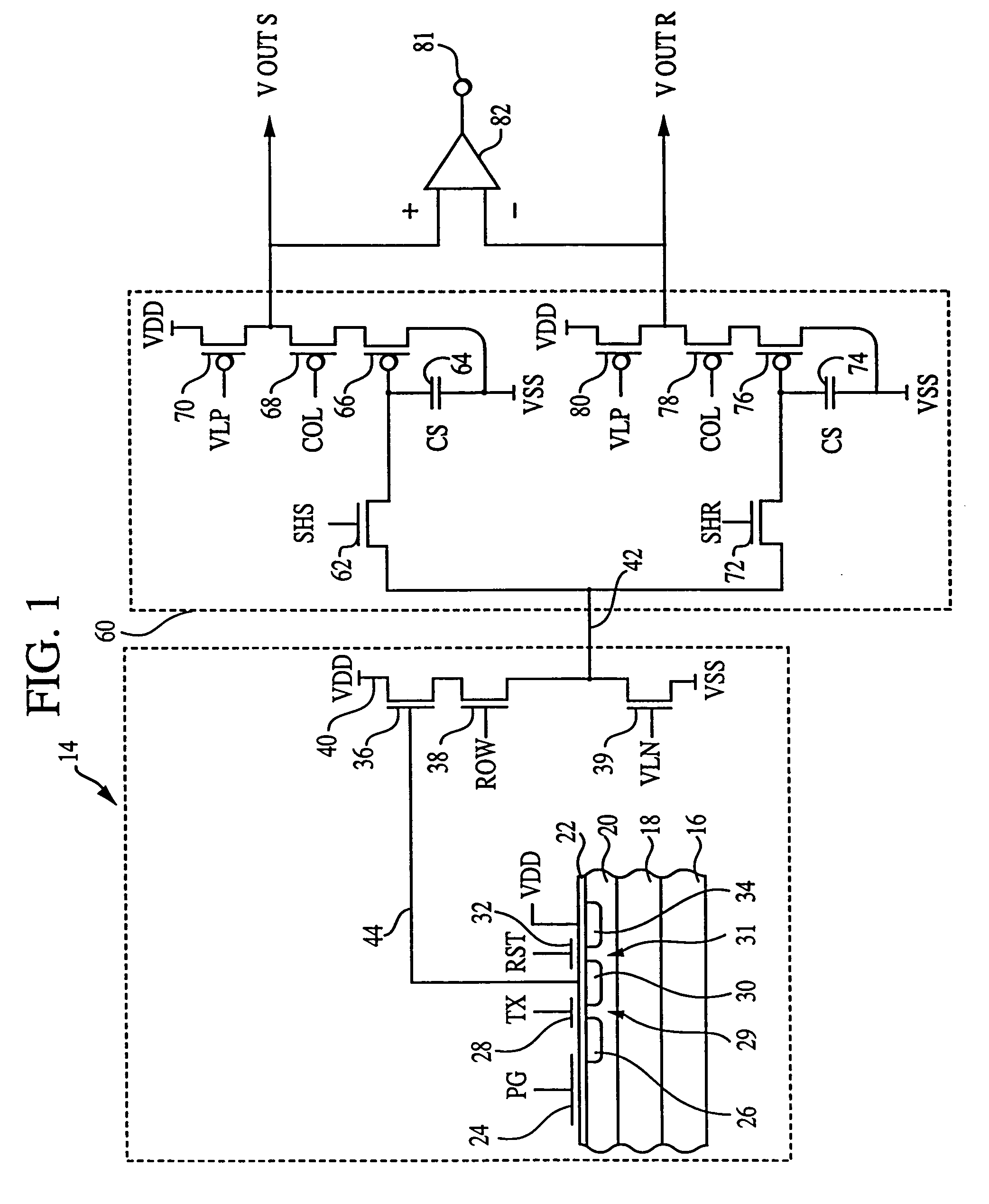
"The present invention provides a pixel sensor cell that has improved quantum efficiency, signal-to-noise ratio, and reduced cross talk. The cell is formed in a retrograde well in a semiconductor substrate. The well has a doped region with a vertically graded dopant concentration that is highest at the bottom and lowest at the surface. The well may also have peripheral circuitry formed therein. The highly concentrated region at the bottom of the well reflects signal carriers back to the photosensor so that they are not lost to the substrate. The invention also provides methods for forming a pixel sensor cell in the retrograde well."

Problems solved by technology

However, CCD imagers also suffer from a number of disadvantages.
For example, they are susceptible to radiation damage, they exhibit destructive read-out over time, they require good light shielding to avoid image smear and they have a high power dissipation for large arrays.
Additionally, while offering high performance, CCD arrays are difficult to integrate with CMOS processing in part due to a different processing technology and to their high capacitances, complicating the integration of on-chip drive and signal processing electronics with the CCD array.
While there have been some attempts to integrate on-chip signal processing with CCD arrays, these attempts have not been entirely successful.
CCDs may also suffer from incomplete charge transfer from pixel to pixel which results in image smear.
Quantum efficiency is a problem in some imager applications due to the diffusion of signal carriers out of the photosite and into the substrate, where they become effectively lost.
The loss of signal carriers results in decreased signal strength, increased cross talk, and the reading of an improper value for the adjacent pixels.

Method used


Image

  • Retrograde well structure for a CMOS imager
  • Retrograde well structure for a CMOS imager
  • Retrograde well structure for a CMOS imager

Examples


Embodiment Construction

[0038]In the following detailed description, reference is made to the accompanying drawings which form a part hereof, and in which is shown by way of illustration specific embodiments in which the invention may be practiced. These embodiments are described in sufficient detail to enable those skilled in the art to practice the invention, and it is to be understood that other embodiments may be utilized, and that structural, logical and electrical changes may be made without departing from the spirit and scope of the present invention.

[0039]The terms “wafer” and “substrate” are to be understood as including silicon-on-insulator (SOI) or silicon-on-sapphire (SOS) technology, doped and undoped semiconductors, epitaxial layers of silicon supported by a base semiconductor foundation, and other semiconductor structures. Furthermore, when reference is made to a “wafer” or “substrate” in the following description, previous process steps may have been utilized to form regions or junctions in...


PUM


Abstract

A retrograde well structure for a CMOS imager that improves the quantum efficiency and signal-to-noise ratio of the imager. The retrograde well comprises a doped region with a vertically graded dopant concentration that is lowest at the substrate surface, and highest at the bottom of the well. A single retrograde well may have a single pixel sensor cell, multiple pixel sensor cells, or even an entire array of pixel sensor cells formed therein. The highly concentrated region at the bottom of the retrograde well repels signal carriers from the photosensor so that they are not lost to the substrate, and prevents noise carriers from the substrate from diffusing up into the photosensor. Also disclosed are methods for forming the retrograde well.

Description

[0001]This application is a divisional of U.S. patent application Ser. No. 10 / 295,952, filed Nov. 18, 2002, now U.S. Pat. No. 6,787,819 which is a continuation of U.S. patent application Ser. No. 09 / 918,450, filed Aug. 1, 2001, now U.S. Pat. No. 6,483,129 which is a divisional of U.S. patent application Ser. No. 09 / 334,261, filed Jun. 16, 1999, now U.S. Pat. No. 6,310,366, each of which is incorporated herein by reference.FIELD OF THE INVENTION[0002]The present invention relates generally to improved semiconductor imaging devices and in particular to a silicon imaging device that can be fabricated using a standard CMOS process.BACKGROUND OF THE INVENTION[0003]There are a number of different types of semiconductor-based imagers, including charge coupled devices (CCDs), photodiode arrays, charge injection devices and hybrid focal plane arrays. CCD technology is often employed for image acquisition and enjoys a number of advantages which makes it the incumbent technology, particularly ...

Claims


Application Information

Patent Timeline
Patent Type & Authority Patents(United States)
IPC IPC(8): H04N3/14H04N3/335H01L31/058H01L21/00H01L27/146H01L27/148H01L31/062H01L31/109H01L31/12H01L33/00H04N25/00
CPCH01L27/14601H01L27/14603H01L27/14609H01L27/14643H01L27/14683H01L27/14689
Inventor RHODES, HOWARD E.DURCAN, MARK
Owner APTINA IMAGING CORP
Features
  • R&D
  • Intellectual Property
  • Life Sciences
  • Materials
  • Tech Scout
  • Unparalleled Data Quality
  • Higher Quality Content
  • 60% Fewer Hallucinations
Learn More