
Using hot swap logic in a communication system

a communication system and logic technology, applied in the field of time division multiplex communication systems, can solve the problems of disruption of data calls in the tdm system, inability to provide a portion of the switched path, and general complexity in the implementation of tdm systems using tsis, so as to enhance various aspects improve the performance of the tdm system, and high clock-to-out times

Inactive Publication Date: 2009-11-17
CISCO TECH INC
View PDF15 Cites 5 Cited by
  • Summary
  • Abstract
  • Description
  • Claims
  • Application Information

AI Technical Summary

Benefits of technology

The present invention provides methods and systems for improving the performance of a TDM system by hot swapping TSIs while compensating for clock distortion and limitations associated with conventional TSIs. This is achieved through the use of hot swap logic that selectively isolates the TSI circuit from the system bus and uses a transmit clock signal to clock signals from the hot swap logic circuit to the system bus and the TSI circuit, as well as a receive clock signal that is related in phase to the transmit clock signal to clock signals from the system bus and the TSI circuit. The hot swap logic circuit can also be used to compensate for clock skew and can be used in a diagnostic evaluation of the TDM system. The technical effects of the invention include improved performance and reliability of the TDM system.

Problems solved by technology

One problem that often arises in TDM systems is that of “blocking.” As known by those skilled in the art, “blocking” arises when one or more stages of switching are introduced between the transmitting and receiving channels, and a portion of the switched path is not available for assignment to a potential connection.
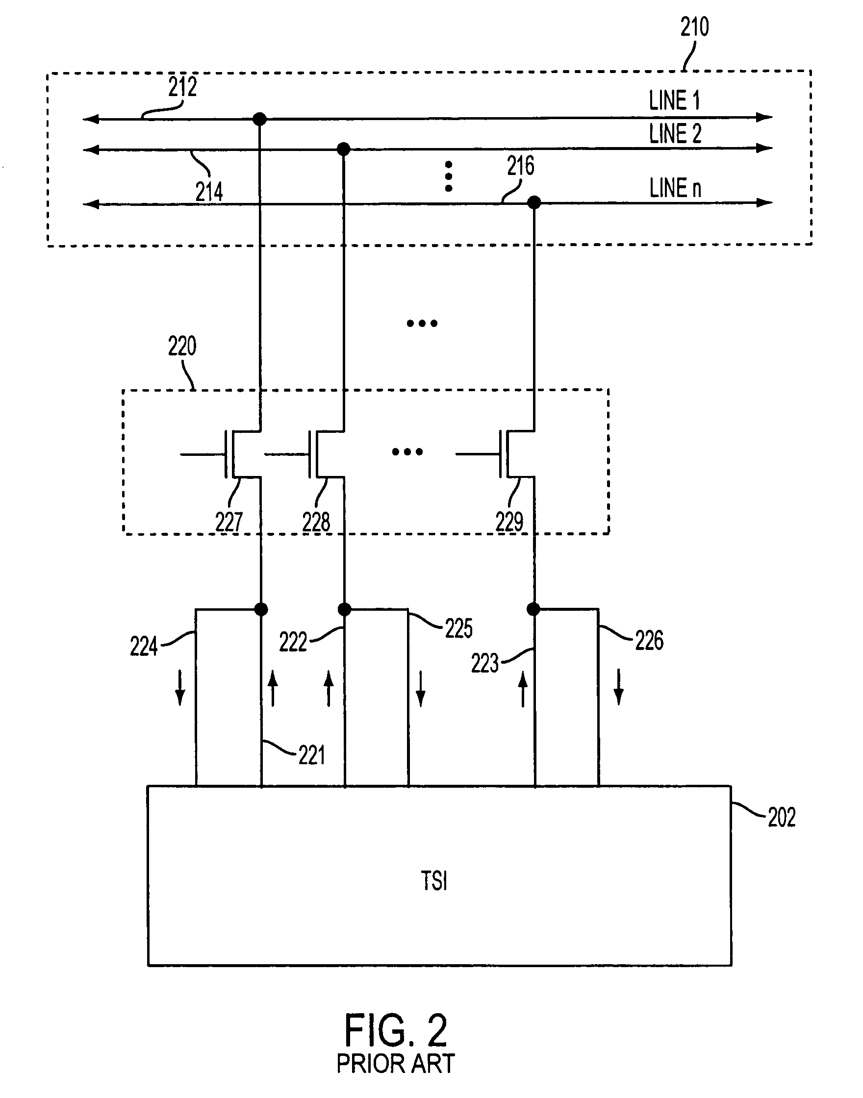
The implementation of TDM systems using TSIs is generally complicated by the fact that off-the-shelf TSI solutions do not incorporate hot swapability into the buffers inside the device.
Therefore, it would be problematic to have TSI 202 reside directly on TDM bus 210.
In the case of telecommunications and other types of systems, such a configuration would be likely to cause disruptions of data calls in the TDM system.
Absent such isolation, a substantial amount of current from other resources in the TDM system could be sunk, resulting in various types of system failures.

Method used


Image

  • Using hot swap logic in a communication system
  • Using hot swap logic in a communication system
  • Using hot swap logic in a communication system

Examples


Embodiment Construction

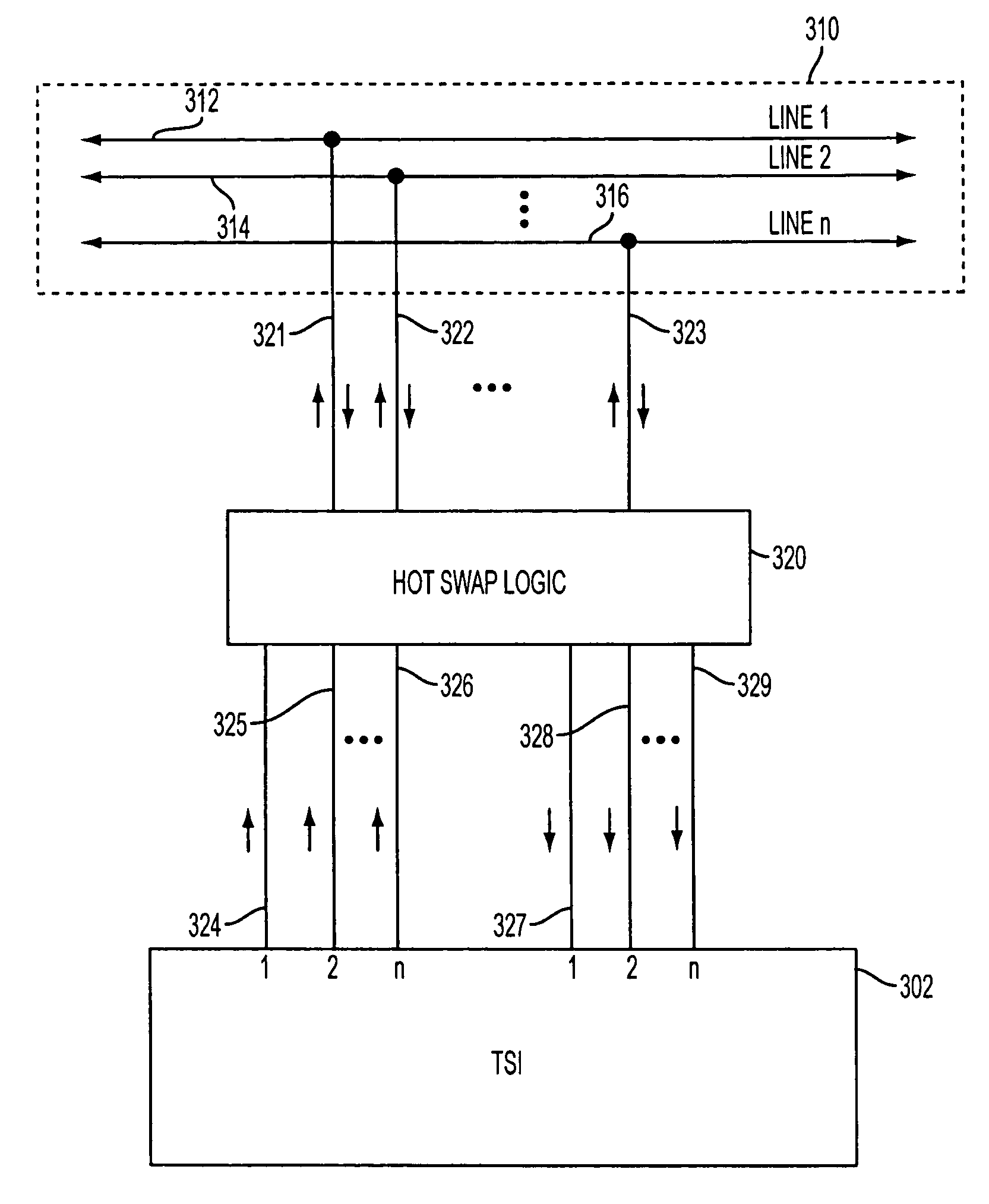
[0030]Methods and systems are provided for providing hot swapability of TSIs in a TDM system. The hot swapability of TSIs is provided using hot swap logic constructed in accordance with the principles of the present invention which, as explained below, also improves the performance of the TDM system.

[0031]FIG. 3 is a simplified illustration of a portion of a TDM system that includes a TSI 302 that is selectively isolated from system TDM bus 310 in accordance with the principles of the present invention. TSI 302 may be any suitable type of TSI that is capable of interchanging time slots of the data signals being distributed on TDM bus 310, which includes n lines 312-316 (where n is any suitable number). It will be understood that, in connection with TSI 302, there are n transmit and receive streams (one transmit and receive stream for each of the n lines in system TDM bus 310). Moreover, each stream going into, or coming out of, TSI 302 has m time slots (e.g., time sliced voice data)...


PUM


Abstract

Methods and systems are provided for providing hot swapability of TSIs in a TDM system using FPGA hot swap logic. The hot swap logic is used to provide isolation for the TSIs from a system TDM bus in the TDM system. Moreover, the hot swap logic is capable of improving the performance of the TDM system. For example, the hot swap logic is capable of compensating for clock distortion associated with the distribution of a common clock signal to various TSIs in the TDM system. Additionally, for example, the hot swap logic is capable of compensating for the limitations imposed in conventional TDM systems due to the relatively high clock-to-out times of conventional TSIs.

Description

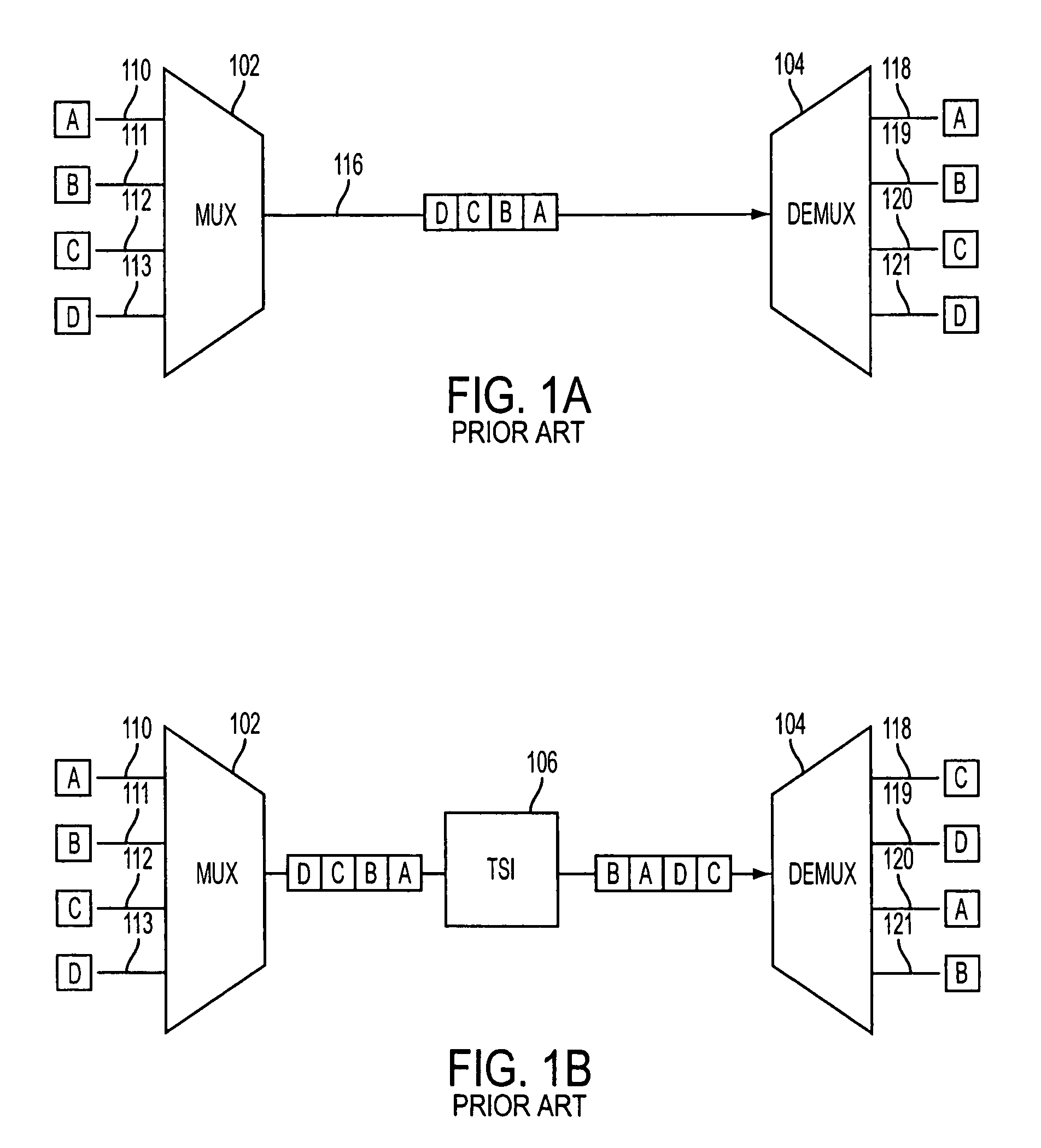
CROSS REFERENCE TO RELATED APPLICATION[0001]This application claims the benefit under 35 U.S.C. § 119(e) of U.S. Provisional Patent Application No. 60 / 487,747, filed Jul. 16, 2003, which is hereby incorporated by reference herein in its entirety.FIELD OF THE INVENTION[0002]The present invention relates to time division multiplex (TDM) communication systems using time slot interchangers (TSIs). More particularly, this invention relates to TDM communication systems employing hot swap logic as buffers between TSIs and a system TDM bus in the communication systems.BACKGROUND OF THE INVENTION[0003]Communication systems have been developed that operate on a time division basis. In these systems, for example, a number of telephone conversations are transmitted on a single, shared communication highway, where each conversation is assigned to the common highway for an extremely short, periodically recurring interval or time slot. Moreover, the connection between any two lines in communicatio...

Claims


Application Information

Patent Timeline
Patent Type & Authority Patents(United States)
IPC IPC(8): H04Q11/00
CPCH04Q11/04H04Q2213/13166H04Q2213/13393H04Q2213/13299H04Q2213/13214
Inventor NIEBEL, WERNER
Owner CISCO TECH INC
Learn More