Bioengineered tissue substitutes

a technology of bioengineered tissue and tissue replacement, which is applied in the field of bioengineered tissue replacement, can solve the problems of eliciting many unfavorable reactions in the body, requiring enormous health care resources to repair and replace diseased tissue structures and organs, and limited lifetimes

Inactive Publication Date: 2009-11-24
UNIV OF WASHINGTON
View PDF13 Cites 33 Cited by
  • Summary
  • Abstract
  • Description
  • Claims
  • Application Information

AI Technical Summary

Benefits of technology

[0026]In another illustrative embodiment, the medical device comprises a scaffold for forming a cartilage substitute. According to this embodiment, the scaffold may comprise one or more layers of one or more arrays of microfibers, wherein the arrays of microfibers are arranged to mimic the configuration of collagen fibers in fibrous cartilage tissue. The medical device comprising a scaffold for forming a cartilage substitute may further comprise cells cultured on the microfiber scaffold to form a cartilage substitute. Typically, the cells in this embodiment comprise chondrocytes. The cells in this embodiments may further comprise fibroblast cells.
[0027]In a further illustrative embodiment, the medical device comprises a scaffold for forming a mitral heart valve. According to this embodiment, the scaffold may comprise one or more layers of a plurality of arrays of microfibers, wherein the plurality of arrays of microfibers are arranged to mimic the configuration of collagen fibers in the mitral heart valve. The medical device comprising a scaffold for forming a mitral heart valve may further comprise cells, such as interstitial valvular cells, fibroblasts, smooth muscle cells, and endothelial cells, cultured on the microfiber scaffold to form an mitral heart valve substitute.

Problems solved by technology

The repair and replacement of diseased tissue structures and organs requires an enormous expenditure of health-care resources.
While there are numerous prosthetic products in use, these also have limited lifetimes and elicit many unfavorable reactions in the body.

Method used


Image

  • Bioengineered tissue substitutes
  • Bioengineered tissue substitutes
  • Bioengineered tissue substitutes

Examples


example 1

Parallel-Fiber Scaffolds for Small Diameter Vessel Substitutes

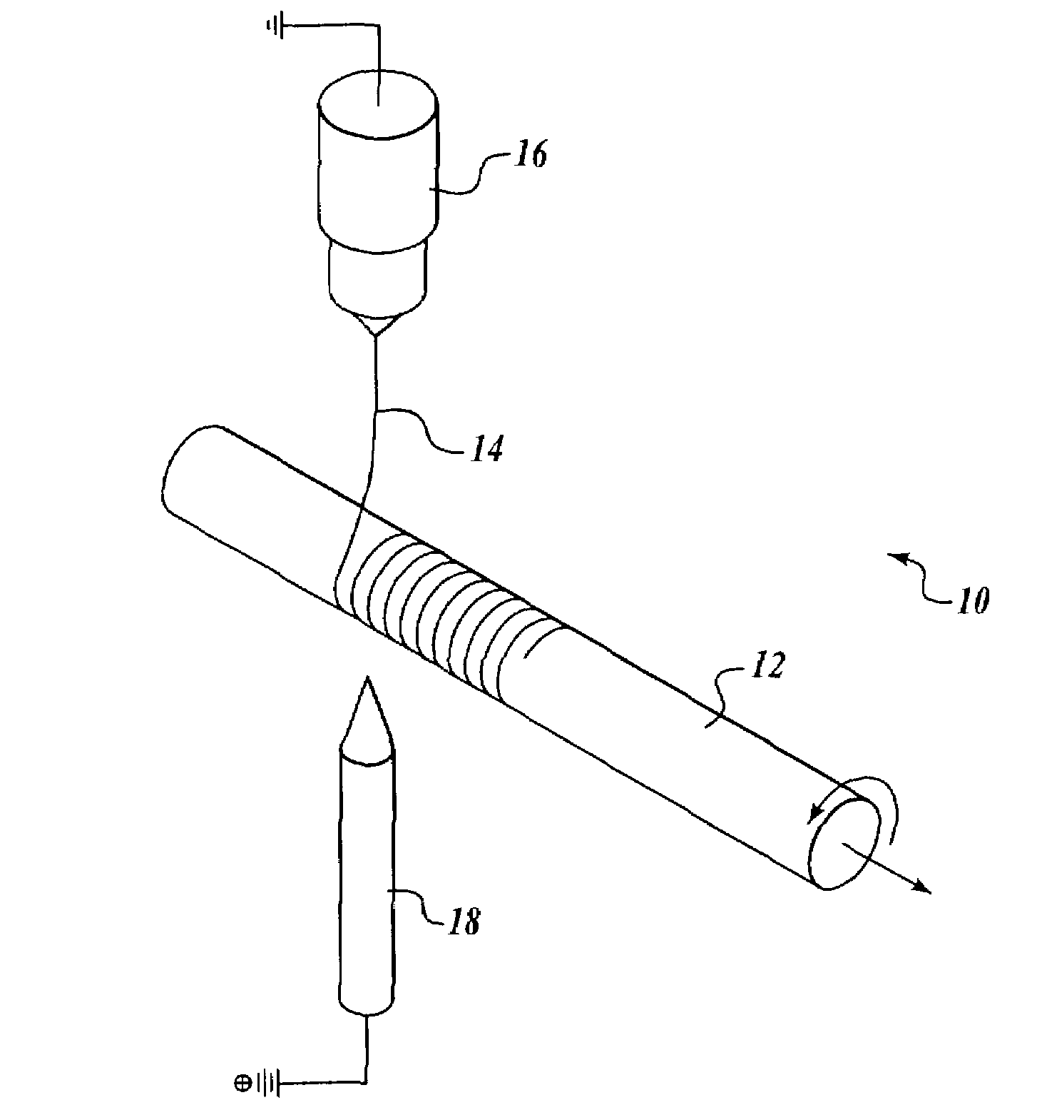
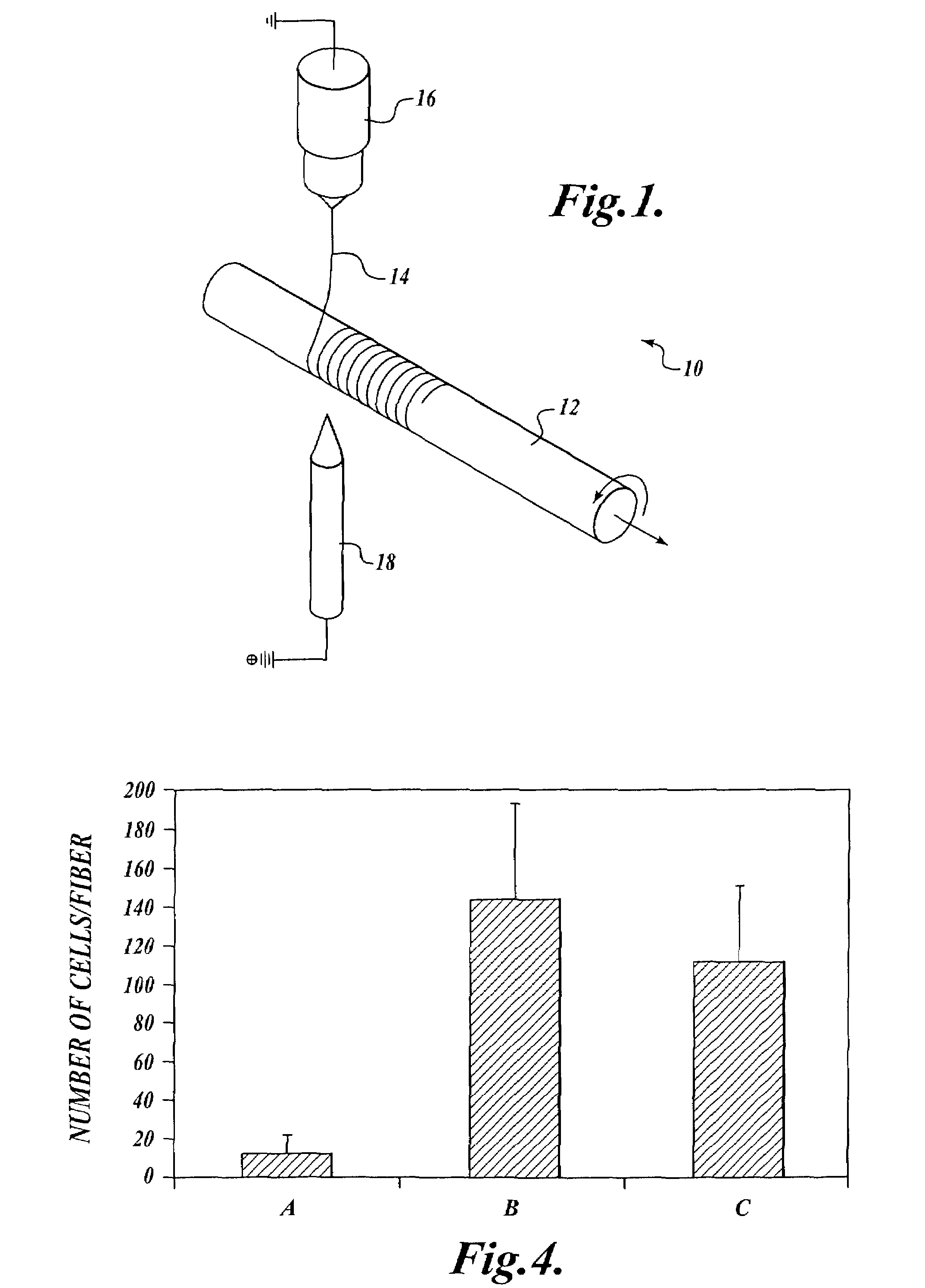
[0122]This Example describes the development of small diameter small diameter blood vessel substitutes using arrays of microfibers that mimic the arrangement of elastin fibers in the medial layer of arterial blood vessels. The arrangement of elastin fibers in the medial layer of arterial blood vessels is shown in FIG. 6.

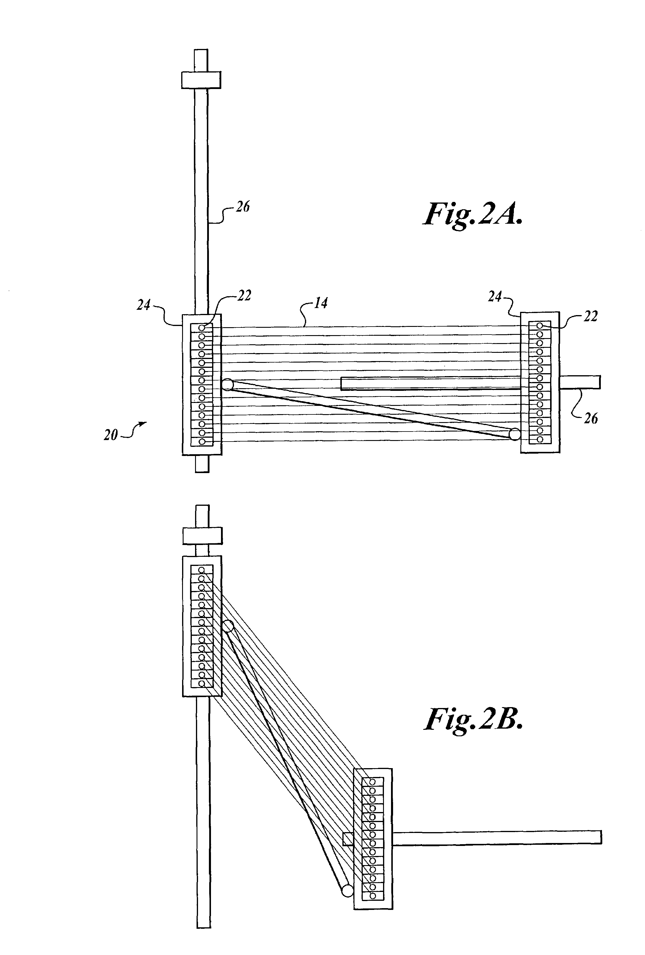
[0123]Parallel microfiber arrays were used as scaffolds to tissue engineer the medial layer of small diameter vessel substitutes. Several questions were addressed to determine whether a parallel-fiber scaffold is a viable approach for enhancing medial layer strength and reducing the time for fabrication of vessel substitutes over current tissue-engineering methods. (1) Is an adhesive protein coating needed to attach cells to the microfibers upon seeding so as to achieve continuous cell layers between adjacent fibers? (2) Fiber spacing is likely critical to the timely formation of robust cell layers between...

example 2

Vessel Substitutes Formed with Tubular Scaffolds

[0139]This Example describes the development of vessel substitutes using tubular scaffolds made from arrays of microfibers that mimic the arrangement of elastin fibers in arterial blood vessels. The experiments described here address the question of whether concentric helices of microfibers be assembled into a scaffold, and if so what strengths may be achieved in a bioengineered, vessel substitute medial layer using such a scaffold. A tubular construct made using concentric helices of 10-micrometers diameter fibers as a scaffold showed elastin fibers aligned with the microfibers at 7 days, with a dense elastin network at 33 days. The burst pressure of the blood vessel substitute at 80 days averaged 3372 mmHg.

A. Materials and Methods

[0140]Tubular scaffolds was created by wrapping concentric layers of microfibers around a mandrel (a thin candy cane), stabilized with longitudinal fibers and end rings. The microfiber arrays were constructe...

example 3

Mechanical Properties of Degradable Polymers for Microfiber Scaffolds

[0144]This Example describes the evaluation of mechanical properties of four different degradable polymers for microfiber scaffolds.

[0145]The ideal material for the microfiber scaffold has the following features: (a) it induces good cell adhesion and spreading upon seeding, facilitating the production and assembly of extracellular matrix proteins; (b) it has degradation byproducts that are not problematic in vivo; (c) it has an initial modulus comparable to or slightly greater than that of elastin, and that reduces over time to effectively transfer load to the bioengineered structure as is matures, and (d) the material is easily manufacturable into different architectures.

[0146]Although initially it would seem logical to use elastin as the scaffold, it is not appropriate for several reasons. The design philosophy is to transfer mechanical load from the substrate to the bioengineered construct as it matures. It is u...


PUM


Abstract

In one aspect, the invention provides methods for forming a target tissue substitute. The methods of the invention comprise the following steps: (a) providing a scaffold comprising one or more layers of one or more arrays of microfibers, wherein one or more of the arrays of microfibers is designed to mimic the configuration of one or more structural elements in a target tissue; and (b) culturing cells on the scaffold to form a target tissue substitute. In another aspect, the invention provides implantable medical devices. The implantable medical devices of the invention comprise a scaffold comprising one or more layers of one or more arrays of microfibers, wherein one or more of the arrays of microfibers is arranged to mimic the configuration of one or more structural elements in a target tissue. Typically, cells are cultured on the scaffold to form a target tissue substitute.

Description

CROSS-REFERENCE TO RELATED APPLICATION[0001]This application claims the benefit of Provisional Application No. 60 / 359,470, filed Feb. 22, 2002, under 35 U.S.C. § 119.GOVERNMENT RIGHTS[0002]This invention was made with government support under R24HL064387 and RO1HD38554 awarded by the National Institutes of Health, and under EEC-9529161 awarded by the National Science Foundation. The government has certain rights in the invention.FIELD OF THE INVENTION[0003]The present invention relates to bioengineered tissue substitutes, such as blood vessel substitutes and muscle substitutes, and methods for forming bioengineered tissue substitutes.BACKGROUND OF THE INVENTION[0004]The repair and replacement of diseased tissue structures and organs requires an enormous expenditure of health-care resources. For example, approximately 500,000 coronary artery bypass surgeries are performed each year in the United States. The most common treatment, replacement with an autograft, produces less than opti...

Claims


Application Information

Patent Timeline
Patent Type & Authority Patents(United States)
IPC IPC(8): C12N5/06A61K35/12A61L27/18A61L27/34A61L27/38C12N5/00C12N5/071C12N5/077
CPCA61L27/18C12N5/0691A61L27/34A61L27/38A61L27/3804A61L27/3852A61L27/3873A61L27/3882A61L27/3886A61L27/3895C12N5/0068C12N5/0658C08L67/04C08L89/00A61K35/12C12N2533/54C12N2533/40
Inventor SANDERS, JOAN E.NEUMANN, THOMAS
Owner UNIV OF WASHINGTON
Why Eureka
Try Eureka