Dynamic voltage scaling for self-timed or racing paths

a self-timed or racing path, dynamic voltage technology, applied in the direction of generating/distributing signals, pulse techniques, instruments, etc., can solve the problems of increasing propagation delay, affecting the performance of self-timed circuits, so as to avoid excessive design margins, minimum required margins, and optimize the effect of self-timed circuit performan

Active Publication Date: 2009-11-24
SUN MICROSYSTEMS INC
View PDF4 Cites 13 Cited by
  • Summary
  • Abstract
  • Description
  • Claims
  • Application Information

AI Technical Summary

Benefits of technology

[0004]This invention optimizes performance of a self-timed circuit by allowing delay of the self-timed circuit to be changed dynamically as a function of operating conditions (e.g., operating voltages or temperature). According to this invention, the delay of a self-timed circuit for a given operating condition may be selected to have the minimum margin for that operating condition among the available delays, at the time the operating condition occurs. The resulting design is an optimal design which avoids excessive design margins for that operating condition. Likewise, the delays of racing paths may be dynamically adjusted as operating conditions change to maintain a minimum required margin.

Problems solved by technology

As the propagation delays of the delay elements vary with PVT conditions, the timing relationships of data and timing signals may not be able to meet design constraints, resulting in glitches or other functional failures.
Generally, at a lower operating voltages, the propagation delay increases.
As a result, under some operating conditions, the included timing margins become unnecessarily large, thereby resulting in a lower (and possibly unacceptable) performance.
In such designs, there is no dynamic flexibility to respond to actual operating conditions.

Method used


Image

  • Dynamic voltage scaling for self-timed or racing paths
  • Dynamic voltage scaling for self-timed or racing paths
  • Dynamic voltage scaling for self-timed or racing paths

Examples


Embodiment Construction

[0011]This invention is applicable to circuits with timing constraints (e.g., a self-timed circuit), and is particularly applicable to such circuits implemented as integrated circuits and systems in which operating voltages and clock frequencies may be varied dynamically according to operating conditions. For example, in a microprocessor suitable for use in a handheld device, the operating voltage and the clock frequencies may be varied based on the microprocessor's processing needs. The ability to adjust these operating conditions—sometimes known as dynamic voltage and frequency scaling (DVFS)—achieves high power efficiency.

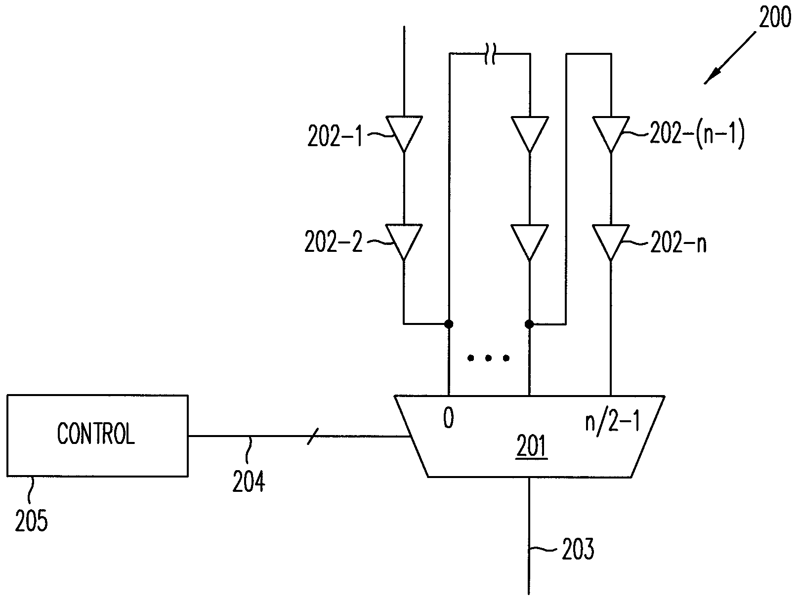
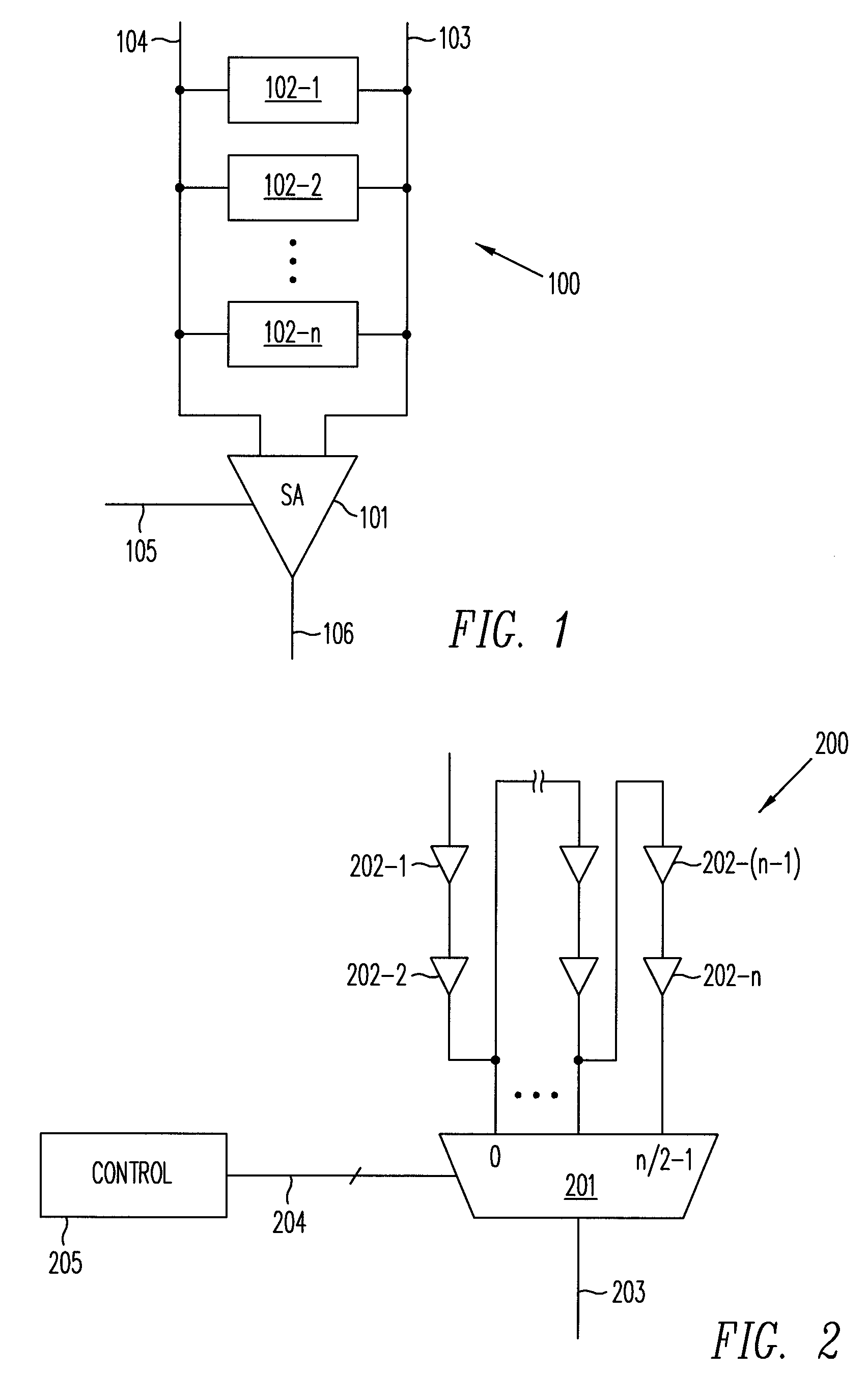
[0012]In one application, a self-timed circuit is provided multiple timing chains for generating timing signals having predetermined delay characteristics for selected operating conditions. During operation, a multiplexer selects a suitable timing signal for the self-timed circuit according to the current operating condition. The operating condition may be a fun...


PUM


Abstract

A timing-constrained circuit (e.g., a self-timed circuit) of optimal performance is achieved by allowing the delay of the circuit to be changed dynamically as a function of operating conditions (e.g., operating voltages or temperatures). The delay of timing signals in the timing-constrained circuit for a given operating condition may be selected to have the minimum margin for that operating condition among the available delays to maximize performance over the entire dynamic range of operating conditions.

Description

BACKGROUND OF THE INVENTION[0001]A robust design for an integrated circuit takes into account a wide range of possible operating conditions, including process variations, operating voltage variations and operating temperatures (“PVT variations”). Such attention is especially required for a signal which timing is tightly constrained (a “timing-constrained signal”; circuits containing such signals are termed “timing-constrained circuits”). Timing-constrained signals include, for example, self-timed signals and racing paths. Self-timed paths are expected to be frequency independent, and all timing constraints on a racing path must be satisfied at all operating conditions. In this regard, racing paths are signal paths that are asynchronous with respect to each other, as to which one or more timing constraints apply. A self-timed path is a signal path in which timing is provided by a locally generated timing signal, rather than by a global clock signal. The timing signal is used, for exa...

Claims


Application Information

Patent Timeline
Patent Type & Authority Patents(United States)
IPC IPC(8): H03K3/00
CPCG11C7/08G11C7/22G11C11/4076H03K19/00384H03K19/018521H03H11/265H03K2005/00019G11C7/04
Inventor BHATIA, AJAYKHANNA, RAJESH
Owner SUN MICROSYSTEMS INC
Why Eureka
Try Eureka