Drying system

a drying system and drying technology, applied in the field of drying systems, can solve the problems of high energy consumption of heating-type drying equipment and hot-wind drying equipment, difficult to do such procedures industrially, and difficulty in achieving the effect of drying system operation efficiency, low water content, and improved quality

Inactive Publication Date: 2009-12-01
GREEN SEIJU CO LTD
View PDF121 Cites 30 Cited by
  • Summary
  • Abstract
  • Description
  • Claims
  • Application Information

AI Technical Summary

Benefits of technology

[0027]The features recited from aspect 2 to the final aspect will provide more advantageous effects. These advantages will now be described for each aspect.
[0028]In the drying system of the second aspect, not only the operating efficiency of the drying system may be enhanced by increasing the total condensation amount, but also obtain an object of lower water content and higher quality by condensing water in the very low temperature near the dew point at the end of the drying operation.
[0029]In the drying system of the third aspect, the heat balance of the compression refrigeration cycle can be controlled optimally through the provision of the second coolant supplying passage.
[0030]In the drying system of the fourth aspect, the amount of heat energy provided by the heating condenser i.e. the amount of heat energy supplied to the object can be controlled.
[0031]In the drying system of the fifth aspect, the heat energy generated by the heating condenser can be efficiently transferred to the object.
[0032]In the drying system of the sixth aspect, the heat energy can be transferred to the whole of the object (W) certainly, uniformly, and rapidly by adding the stirrer for stirring and the assister for assisting the heat transfer.

Problems solved by technology

However, it is difficult to do such procedures industrially, since vast amount of grounds and long time is required therefor.
Whereas, heating-type drying equipment and hot-wind drying equipment energy must waste great amount of energy, since hot waste gas including water steam must be drained.
Furthermore, vacuum drying equipment, as another drying procedure, is still problematic on its operation, operating cost, and the ease of handling thereof.
Therefore, unless the temperature of the object is lower than that of the hot air and the object is contacted with the air sufficiently, the air of warm, light, and low humidity races between the object and the evaporator, thus extremely decreasing water condensing efficiency.
(1) The capacity of the refrigeration cycle can not be used with practical efficiency due to the lack of control mechanism for optimizing the flow rate. The efficiency for condensing water vapor is highly reduced as the water content of the object is lowered and the relative humidity of the circulating air is reduced.
(2) The refrigeration cycle can not be operated constantly or normally, since the heat balance of the system is not controllable. Otherwise, the mechanism required for controlling the heat balance is so complex that it is difficult to produce the mechanism in a practical cost.
(3) Objects can not be assumed with high quality, since the amount of heat energy used for heating the objects are not controllable.
(4) The capacity of the refrigeration cycle can not be used with practical efficiency due to the lack of the means for enhancing the amount of water vaporized in a unit of time. Although there are thought a variety of means for facilitating the evaporation, the practicability can not be achieved unless the evaporation capacity suitable for the refrigeration cycle is provided through either one or all of the evaporation facilitator.

Method used


Image

  • Drying system
  • Drying system
  • Drying system

Examples


first embodiment

[0047]the invention will now be described with reference to FIGS. 1-3.

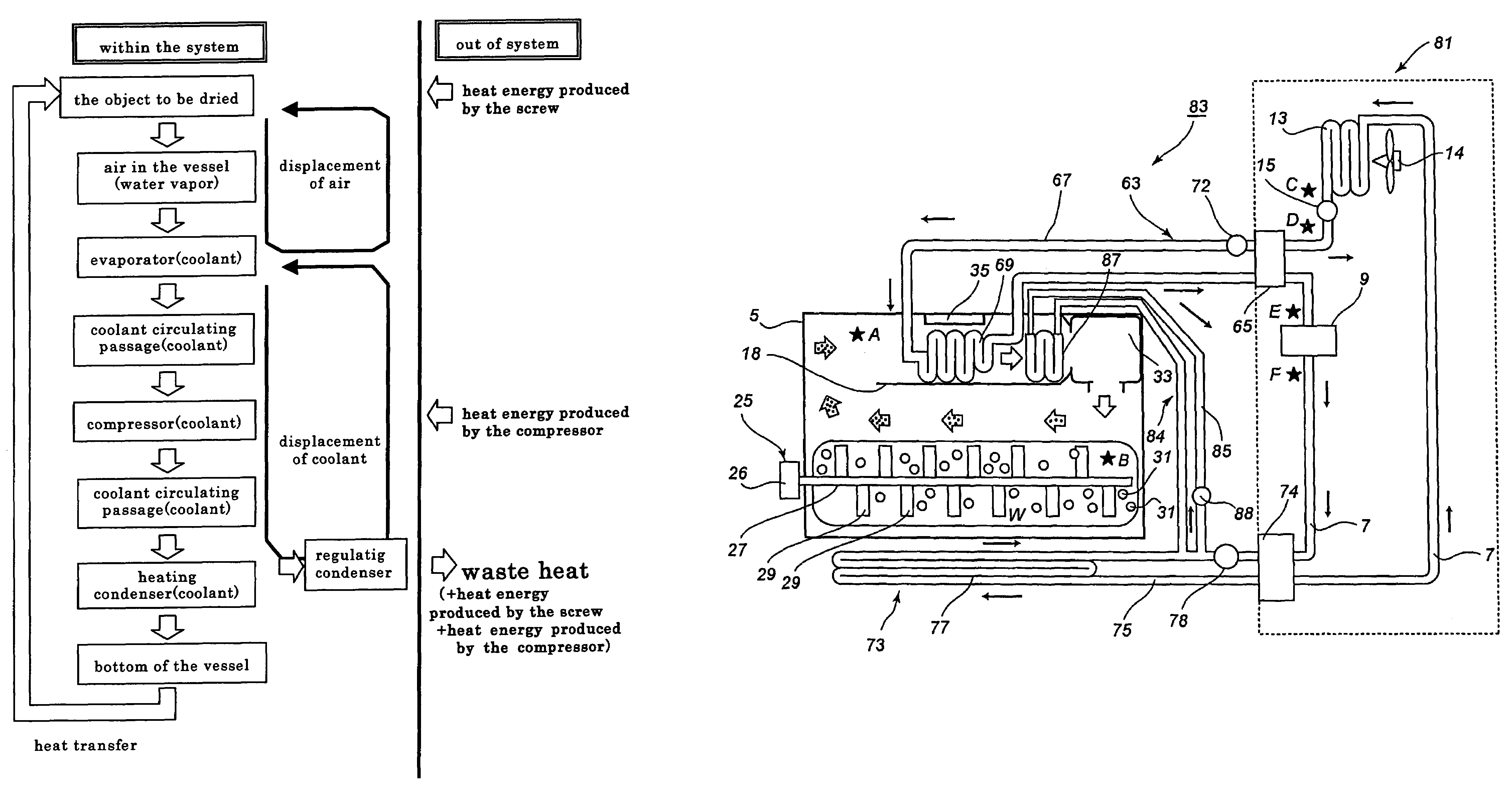
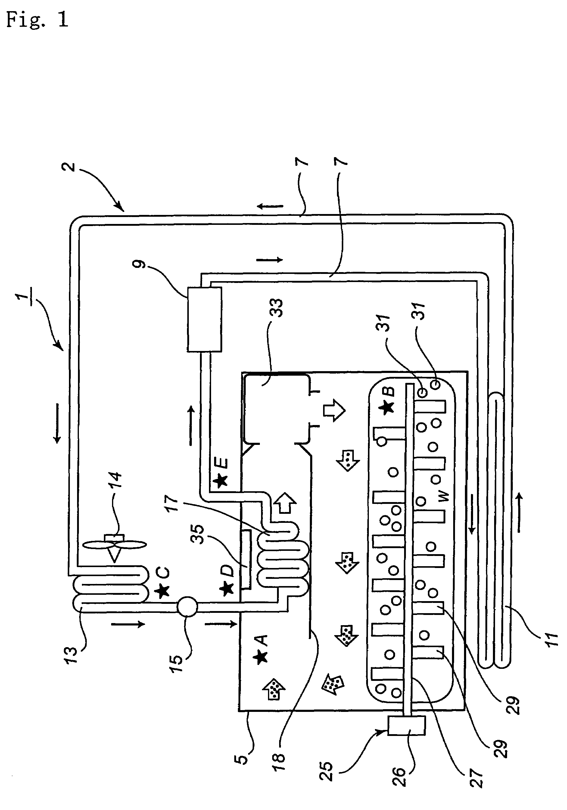
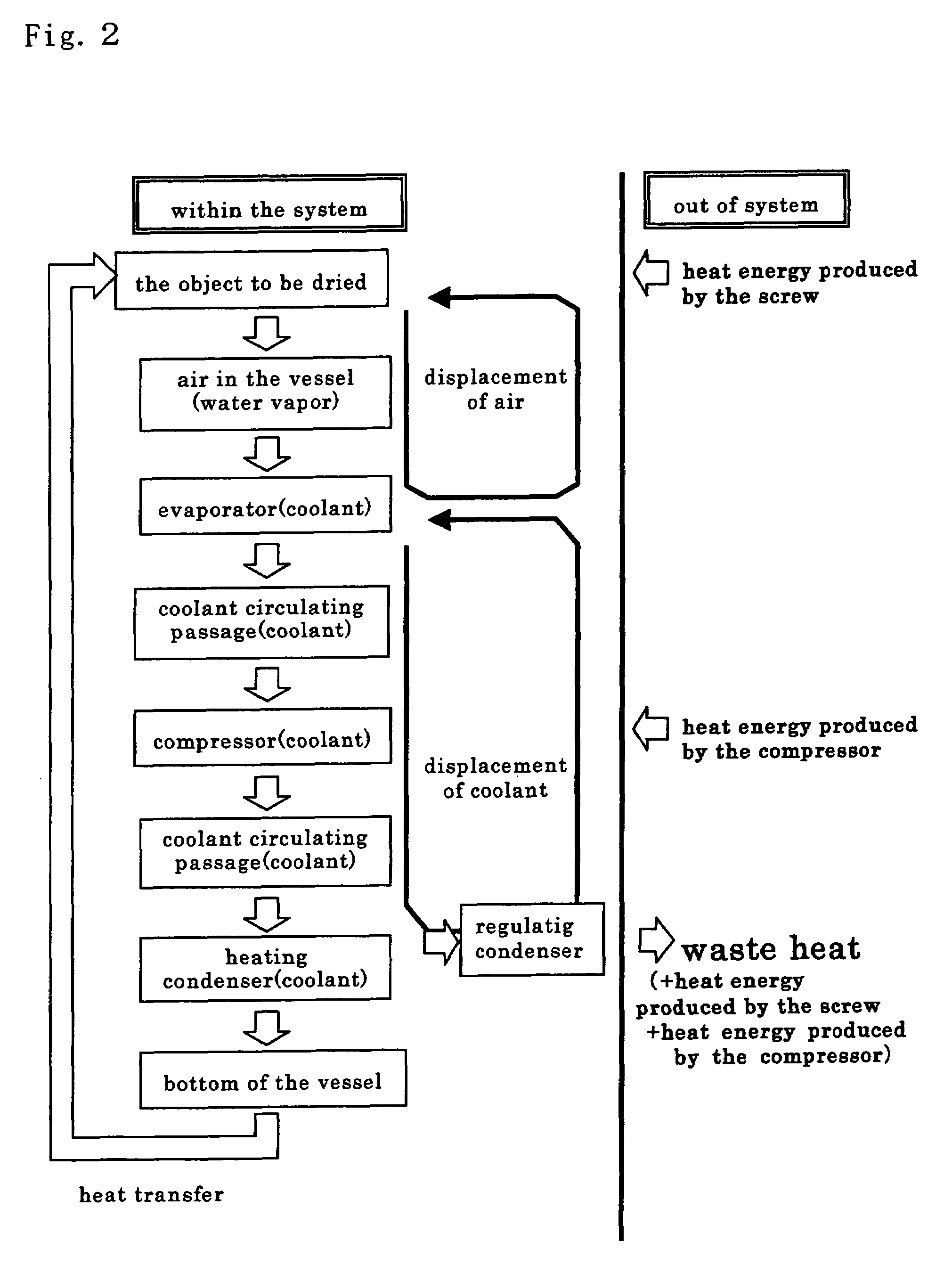
[0048]FIG. 1 is a diagrammatic view illustrating the drying system in accordance with the first embodiment, FIG. 2 is a flow diagram illustrating the cycle of heat transfer, and FIG. 3 is a block diagram illustrating the system for controlling the drying system of the invention.

[0049]In this embodiment, an object (W) to be dried is tea leaves, which represent moist organic materials.

[0050]Essential components of the drying system 1 are compression refrigeration cycle section 2 and processing vessel 5. In this drying system 1, the cooling and heating operations are effected on direct modes, respectively.

[0051]At first, the arrangement and the operation of the compression refrigeration cycle section 2 are described in detail.

[0052]The section 2 is provided from the upstream side thereof with a compressor 9, a heating condenser 11, a regulating condenser 13, an expansion valve 15, and an evaporator 17 in this sequenc...

second embodiment

[0095]The drying system 41 in accordance with the second embodiment will now be described with reference to FIG. 4. This figure is a diagrammatic view generally illustrating the drying system 41. The structural components of the drying system 41 illustrated in FIG. 4 are designated by the same reference numeral as those used in FIG. 1, provided that those corresponding components are substantially identical with each other. In this connection, the description is omitted on the corresponding components.

[0096]The drying system 41 is provided with the first flow passage (coolant circulating passage 7) for delivering coolant from the compressor 9 to the heating condenser 11, and the second flow passage (by-pass passage) 43 in parallel with the first one for delivering coolant directly into the regulating condenser 13. The second flow passage is provided with a flow control valve 45. When it is almost unnecessary to increase the temperature of the object (W), the divergence of the flow c...

third embodiment

[0098]The drying system 51 of the third embodiment will now be described with reference to FIG. 5.

[0099]FIG. 5 is a diagrammatic view generally illustrating the drying system 51. The structural components of the drying system 51 illustrated in FIG. 5 are designated by the same reference numeral as those used in FIG. 1, provided that those corresponding components are substantially identical with each other. In this connection, the description is omitted on the corresponding components.

[0100]The principal aspect of the drying system 51 is a reheating section 52. The coolant of high temperature and high pressure flows from the compressor 9 through the flow passage 7 and into the heating condenser 11 to provide heat energy to the object (W) through liquefying the coolant. The reheating section 52 connected in series with the heating condenser 11 includes a reheating element 55 for heating air immediately after passing through the evaporator 17. The amount of heat energy to be supplied ...


PUM


Abstract

In a drying system using a compression refrigeration system, a condenser is divided into a regulating condenser and a heating condenser. The regulating condenser is capable of regulating the amount of exhaust heat discharged to outside the system. The heating condenser produces moist air by feeding heat to an aqueous object to be dried placed in a processing vessel to evaporate the moisture in the object. Heat of condensation of steam is recovered by an evaporator as heat of a refrigerant, and the recovered heat is discharged in the heating condenser to use it for the vaporization of the moisture in the object, and excess heat is discharged by the regulating condenser to outside the system.

Description

FIELD OF THE INVENTION[0001]The present invention relates to a drying system. More particularly, the invention relates to a closed drying system using a compression refrigeration cycle of high energy efficiency to reduce affect on the environment.DESCRIPTION OF THE PRIOR ART[0002]Sun-drying or air-drying procedures have previously been done. Such procedures can dry with high quality, provided that rotting is prevented. However, it is difficult to do such procedures industrially, since vast amount of grounds and long time is required therefor. Further, such procedures are also depending on weather. Whereas, heating-type drying equipment and hot-wind drying equipment energy must waste great amount of energy, since hot waste gas including water steam must be drained. Furthermore, vacuum drying equipment, as another drying procedure, is still problematic on its operation, operating cost, and the ease of handling thereof.[0003]Japanese Patent Laid-Open Public Disclosure Hei. 11-63818 (19...

Claims


Application Information

Patent Timeline
Patent Type & Authority Patents(United States)
IPC IPC(8): F26B3/00F26B11/14F26B21/08F26B21/04F26B25/00
CPCF26B3/205F26B23/005F26B21/086Y02B30/52Y02P70/10
Inventor KONABE, AKIHISAKUROBE, ISAO
Owner GREEN SEIJU CO LTD
Why Eureka
Try Eureka