Reactor assembly

a technology of assembly and reactor, which is applied in the direction of gas-gas reaction process, laboratory glassware, instruments, etc., can solve the problems of increasing the difficulty of analysis accuracy, increasing the difficulty of analyzing the composition of the effluent stream, and many problems, so as to increase the volume of fluid, increase the efficiency of the gas liquid separator, and reduce the effect of aging

Active Publication Date: 2009-12-01
AVANTIUM TECH +1
View PDF13 Cites 7 Cited by
  • Summary
  • Abstract
  • Description
  • Claims
  • Application Information

AI Technical Summary

Benefits of technology

[0020]In the reaction zone, gaseous and liquid components can be formed at the reaction conditions used. A gas / liquid mixture often leads to measurement inaccuracies, e.g. by the formation of a slug of gas, followed by a slug of liquid in the effluent stream, resulting in pressure variation in the stream and a non-constant flow thereof, leading to measurement inaccuracies. Further, another problem, caused by the presence of gas in a liquid effluent stream is the fact that liquid analysers, such as GC or HPLC systems cannot properly be used when gas-bubbles are present in the liquid stream. Gas-bubbles will cause a variation of the amount of liquid injected in such systems. Further, the presence of gas in the inlet capillary of a mass spectrograph will cause strong measurements fluctuations and also, spectroscopic techniques, such as Ultraviolet-Visible spectroscopy, Near Infrared spectroscopy or Infrared spectroscopy will strongly suffer from light scattering and liquid displacement because of the presence of gas. Further, for proper testing / screening, the determination of the production rate of gaseous compounds as well as of liquid compounds and quantification thereof is necessary for accurate analyses of the reaction process. It is therefor highly advantageous to separate the liquid and the gaseous components in the effluent stream from each other before being transferred to an analyser. An additional advantage of the invention is the fact that due to the addition of diluent the volume of the effluent stream is considerably increased. This will allow the use of G / L separators with larger internal dimensions without causing unnecessary hold-up of the products. Thus, the effluent conduit preferably comprises a gas / liquid separator, therewith enabling proper separation of the gaseous and liquid components from one another, so that the gaseous phase can be analysed independently from the liquid phase. It is however also possible to discard either one of the said phases and to analyse the not-discarded phase. In some cases it is necessary to add a gas / liquid separator before discharging the effluent to an analyser. This is the case when the reactor effluent consists of a gas and a liquid phase, but also will be necessary when the reactor effluent consists of only liquid and a gas diluent is added, or when the reactor effluent consists of only gas and a liquid diluent is added.
[0021]The gas / liquid separator will have at least two outlets, one predominantly containing gas and one predominantly containing liquid, each discharging to a separate analyser. The efficiency of the gas liquid separator is strongly dependent on its size. As the volume of fluid is increased by the addition of diluent, as described in the present invention, it allows the use of a larger gas / liquid separator thus increasing its efficiency.
[0022]In order to quantitatively analyse the gaseous or liquid stream, it is of importance that the gas / liquid separator is capable of completely separate the gaseous from the liquid flow. However, such a separation requires high sophisticated gas / liquid separator equipment. In a very attractive embodiment of the present invention, at least two gas / liquid separators are present in the effluent stream, arranged to one another in a serial fashion. In the first upstream separator, a representative amount of either gas or liquid is separated from the remaining effluent stream, that still may comprise a mixture of both gas and liquid. The separated gas or liquid can then be analysed accordingly. In the second, downstream gas / liquid separator, a gaseous flow is separated in case in the first separator liquid was separated or, when in the first separator gas was separated, liquid will be separated in the second gas / liquid separated, possibly leaving a stream still containing gas and liquid effluent leaving the separator. In this way, both gaseous and liquid effluent components can be properly analysed, without the need of sophisticated gas / liquid separation devices. Such devices may in this arrangement be of more simple design, as full separation of gas and liquid is not required. Any not separated gas / liquid mixture can be discarded. Analysis and quantification of the compounds of the effluent stream are preferably performed by incorporation, in the effluent stream, of an internal standard, preferably comprising both a liquid and a gaseous internal standard (see below).
[0023]Preferably, the analyser is chosen from the group, consisting of: gas chromatograph (GC), liquid chromatograph (LC), high pressure liquid chromatograph (HPLC), a mass spectrometer (MS), a diffractometer, an Ultraviolet-Visible (UV-VIS) spectrometer, a Infrared (IR) spectrometer, a Near Infrared (NIR) spectrometer, a Nuclear Magnetic Resonance (NMR) spectrometer, a viscosity meter or density meter.Preferably, the analyser comprises on-line analyser or a sample collection system, or a combination thereof.
[0024]Non-limiting examples of on-line analysers are a gas chromatograph (GC), liquid chromatograph (LC), high pressure liquid chromatograph (HPLC), a mass spectrometer (MS), a diffractometer, an Ultraviolet-Visible (UV-VIS) spectrometer, a Infrared (IR) spectrometer, a Near Infrared (NIR) spectrometer, a Nuclear Magnetic Resonance (NMR) spectrometer, a viscosity meter, density meter. These analyzers may be equipped with a sample valve or syringe injection system to allow injection of a small representative sample of the effluent stream.
[0025]As mentioned above also a sample collection system can be used for the analysis of samples. In that case the samples are first collected in collection containers before being transferred to one or more analysers. Thus will allow more flexibility of the system, as it is not necessary to integrate the analyser in the whole apparatus. The sample collection system is designed in such a way that it can collect liquid samples in collection containers designed to collect liquids, or it can collect gaseous samples in collection containers designed to collect gas. Examples for liquid collection containers are reactor tubes, vials, wells or the like. Examples for gas collection containers are gas-collection bags (Tedlar bags), gas-tubes, gas pipettes, cold traps, cryogenic traps or the like. The collection containers may be organised in a systematic way, such as for instance in a row, a matrix or a carrousel. Typical examples of such systems are reagent tube racks, 96-well plates, 384-well plate, auto-sampler racks, or carrousel. Most modern analyser systems known in the art are equipped with a so-called auto sampler allowing automatic analysis of a multitude of samples. Preferably the array of collection containers of such collection system is configured in such a way that it is compatible with the auto-samplers of the consecutively used analyser system.

Problems solved by technology

However, numerous problems often occur when using reactor assemblies known in the art.
Especially when analysing a small amount of effluent stream, in particular when operating with a liquid flow rate of less than 1.0 ml / min / reactor, in particular less than 0.5 ml / min, and / or a gas flow rate of less than 100 Nml / min / reactor, in particular less than 50 Nml / min / reactor as is often the case in so called high-throughput experimentation as described in WO 99 / 64160, it has been proven to be very difficult to analyse the composition of the effluent stream in an accurate manner.
The term “Nml” means the volume of the gas at 1 atm and 20° C. The accuracy of the analyses tends to be more difficult when smaller amounts of effluent stream are available for analyses.
It has e.g. been found that a significant amount of effluent stream may remain in the reaction chamber, e.g. due to adhesion of one or more of the components, present in the effluent stream, to the wall of the reaction chamber, leading to measurement inaccuracies.
Further this may also cause an undesired time delay between the moment the efficient stream leaves the reaction zone and the moment the reactants of the said steam arrive at an analyser, which is highly undesired for high-throughput experimentation.
Further, it is not possible to conduct accurate measurements on e.g. concentration, fluxes and production rate when a small amount of effluent stream is available for analyses.
A particular problem occurs when dealing with gas / liquid mixtures exiting the reactor, especially when dealing with the low flow rates as mentioned above.
Gas / liquid separation, which is essential for subsequent analysis of both phases, is very difficult on the small flows to be separated.
The small dimensions of such G / L separators will cause adhesive forces such as capillary force and surface tension effects to dominate over gravity, and as such will hinder easy separation based on gravity.

Method used


Image

  • Reactor assembly
  • Reactor assembly
  • Reactor assembly

Examples


examples

[0134]The reduction of 3-hexen-2-on to 3-hexen-2-ol was performed both in gas phase as in trickle flow mode. A fixed reaction pressure of 10 bar and a reaction temperature of 100° C. was chosen in both cases. The saturated vapour pressure of 3-hexen-2-ol at 100° C. is approximately 20 kPa and at 25° C. it is 0.3 kPa.

Example: 1 Reduction of 3-hexen-2-on to 3-hexen-2-ol in the Gas Phase

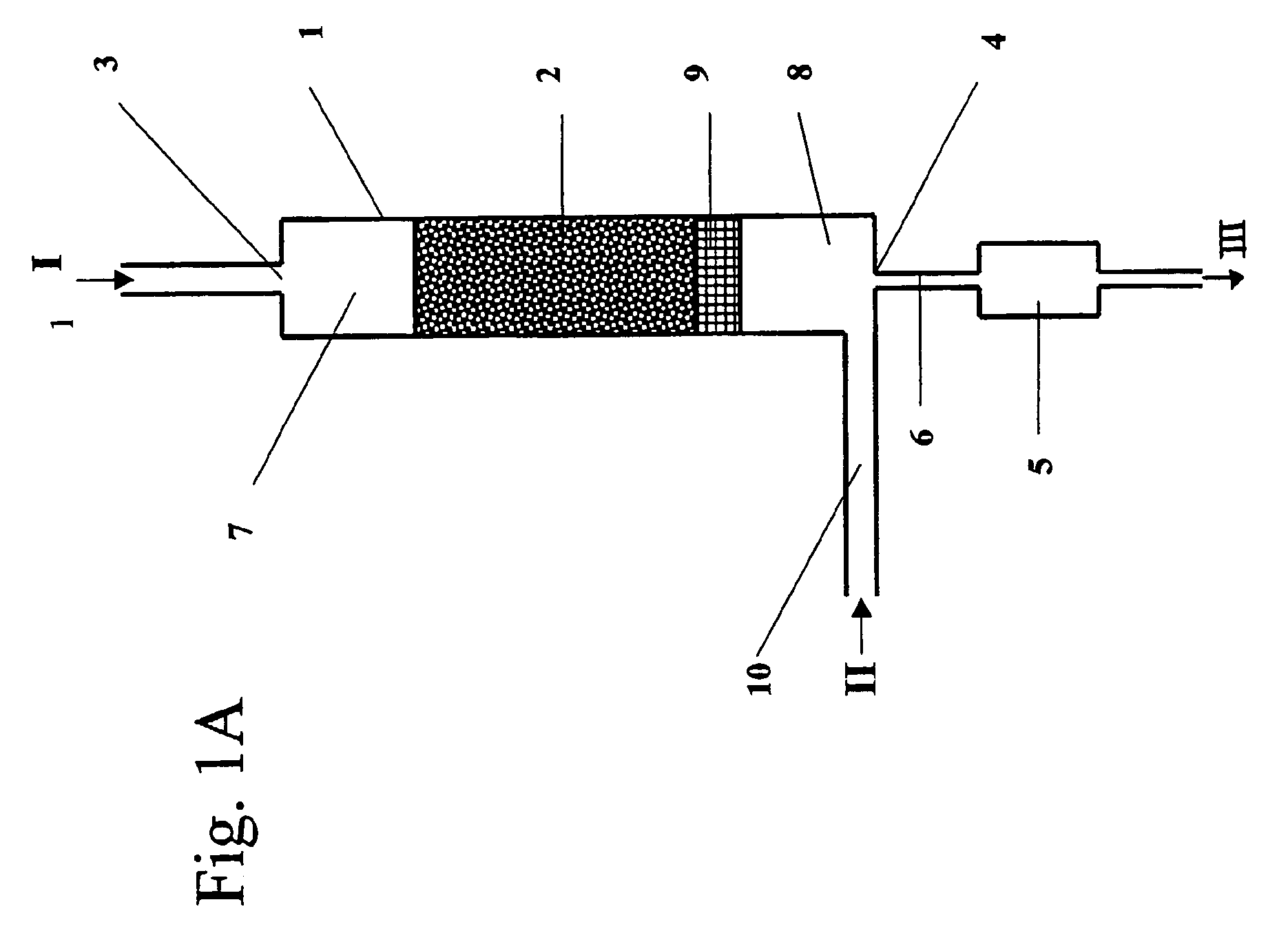
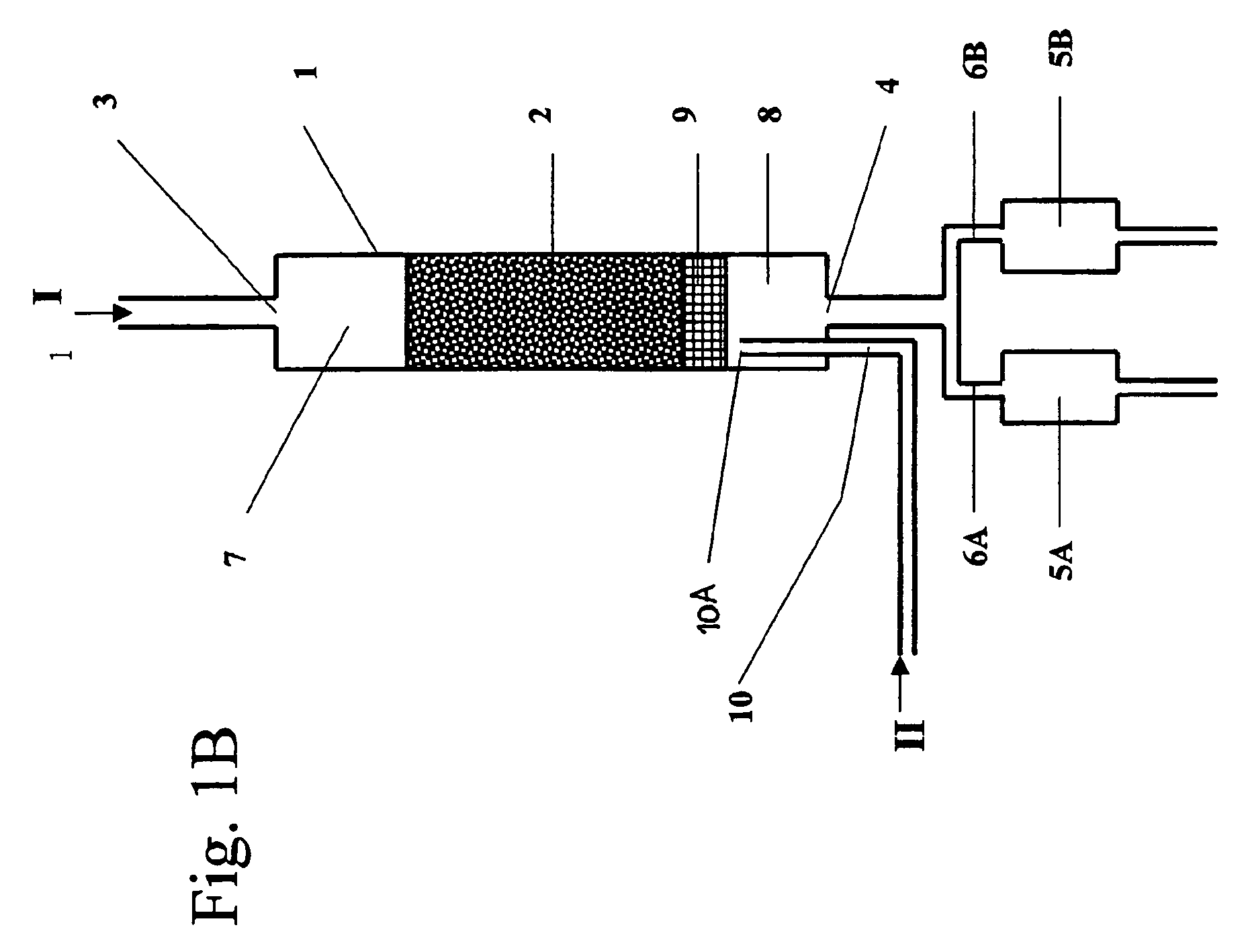
[0135]The reactor set-up as shown in FIG. 1e and FIG. 7 without however the presence of a gas / liquid separator and a liquid analyser. The equipment was equipped 64 reactors in parallel with one GC.

[0136]A library of heterogeneous catalysts with a wide variation in chemical composition was loaded in the reactors. The amount of catalyst was 100 μg per individual reactor. 5 Nml / min / reactor (0.2 mmol / min / reactor) of hydrogen gas and 0.004 mmol / min 3-hexen-2-on liquid feed was fed to each reactor. Thus the gas in the reaction zone may just consist of 2 v % 3-hexen-2-ol.

[0137]The reaction mixture flowing out ...

example 2

of 3-hexen-2-on to 3-hexen-2-ol in the Trickle Phase

[0139]By adding significantly more 3-hexen-2-on the majority of the reactant will remain in the liquid phase, causing the reactant to trickle through the catalyst bed. The term “trickle phase” means that a mixture of gas and liquid is fed to a reaction zone, wherein the liquid passes (trickles) through the said zone by gravity force. In this experiment a 3-hexen-2-on feed of 0.083 mmole / min / reactor (20 times more then in the preceding example) was used. To the outlet of each reactor di-isopropylether diluent was added at 100 mg / min / reactor using a pump and a distributor with capillaries. The diluent contained 0.0.085 mole % of hexadecane internal standard. The hexadecane flow rate was 0.83 micromole / min. To the liquid reactor feed also 1 vol % heptadecane was added as an internal standard. This internal standard together with the hexadecane standard allows us to monitor the ratio of the reactant flow rate and the diluent flow rate ...


PUM

PropertyMeasurementUnit
gas flow rateaaaaaaaaaa
diameteraaaaaaaaaa

Abstract

A reactor assembly for analysing the effluent stream from at least one flow-through reactor, The reactor includes a flow-through reactor for performing at least one chemical reaction. The flow-through reactor includes a reaction chamber including a reaction zone, the reaction chamber being connected to a reactor inlet for a reactant, upstream of the reaction zone and a reactor outlet for the effluent stream from the reaction zone, downstream of the reaction zone; and an analyser for subjecting the effluent stream to an analysing procedure, each reactor outlet being connected to an analyser by an effluent conduit. The reactor assembly further includes a dilution fluid supply member for adding a dilution fluid to the effluent stream, downstream of the reaction zone.

Description

FIELD OF THE INVENTION[0001]The invention relates to a reactor assembly for analysing the effluent stream from at least one flow-through reactor. The invention further relates to a process for analysing a fluid effluent stream from a flow-through reactor.BACKGROUND OF THE INVENTION[0002]Reactor assemblies are known in the art for e.g. testing optimal reaction conditions for chemical reactions, including biological and pharmacological processes, such as testing the pharmacological activity of a test compound, the activity of a catalyst or enzyme, optimal reaction parameters etc. E.g. WO 99 / 64160 (herein incorporated by reference) describes a reactor assembly of the above-mentioned kind for testing and / or screening a collection of compounds in order to find the optimal reaction conditions and performance of the said compounds. As the reactor assembly is designed for testing and or screening purposes and not for production purposes, the reactor outlets are connected to an analyser, whe...

Claims


Application Information

Patent Timeline
Patent Type & Authority Patents(United States)
IPC IPC(8): B01J19/00B01J10/00G01N15/06B01L3/00C40B30/08C40B40/18C40B60/14G01N1/34G01N31/10
CPCB01J19/0046G01N31/10B01L3/5025G01N1/405B01J2219/00306B01J2219/00308B01J2219/00313B01J2219/00331B01J2219/00333B01J2219/00351B01J2219/00495B01J2219/00585B01J2219/00702B01J2219/0072B01J2219/00745B01J2219/00747B01L2300/04B01L2300/0867C40B30/08C40B40/18C40B60/14B01J2219/00286B01J2219/00423C40B60/12
Inventor VAN DEN BRINK, PETER JOHNBRACHT, MAARTENGRUTER, GERARDUS JOHANNES MARIADE RUITER, RENEHARJI, BASHIR HUSEIN
Owner AVANTIUM TECH
Why Eureka
Try Eureka