Drilling riser buoyancy modules

a technology of riser and buoyancy module, which is applied in the direction of waterborne vessel navigational aids, special-purpose vessels, transportation and packaging, etc., can solve the problems of increasing the cost of oil, affecting the performance of the product, and affecting the quality of the product, so as to achieve superior performance and manufacturability.

Inactive Publication Date: 2009-12-08
CUMING CORP
View PDF10 Cites 35 Cited by
  • Summary
  • Abstract
  • Description
  • Claims
  • Application Information

AI Technical Summary

Benefits of technology

[0002]Drilling riser buoyancy for subsea oil production has traditionally been produced using fiberglass skins. This invention used a polymer shell coating over a solid syntactic foam that is formed into the shape required and filled with the buoyant material. This method produces a product that is superior in both its performance, as well as, manufacturability.

Problems solved by technology

Previous products are subject to damage as the pipe and buoyancy are handled and as they travel through the diverter housing during installation.
They are also subject to damage during installation on the drilling riser and during handling of the dressed pipe.
That amount is rising as the cost of oil rises.

Method used


Image

  • Drilling riser buoyancy modules
  • Drilling riser buoyancy modules
  • Drilling riser buoyancy modules

Examples


Embodiment Construction

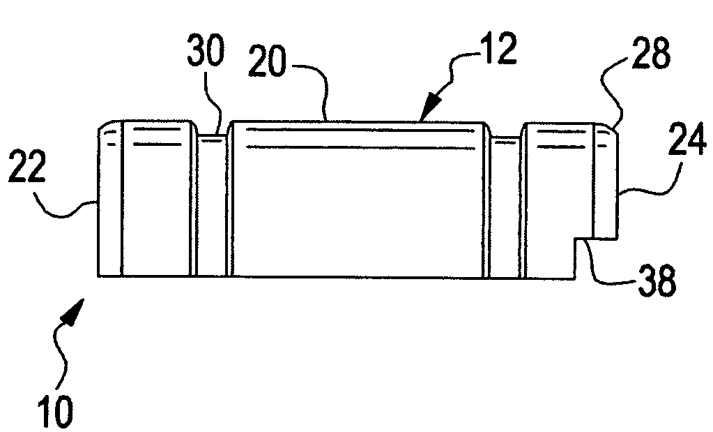
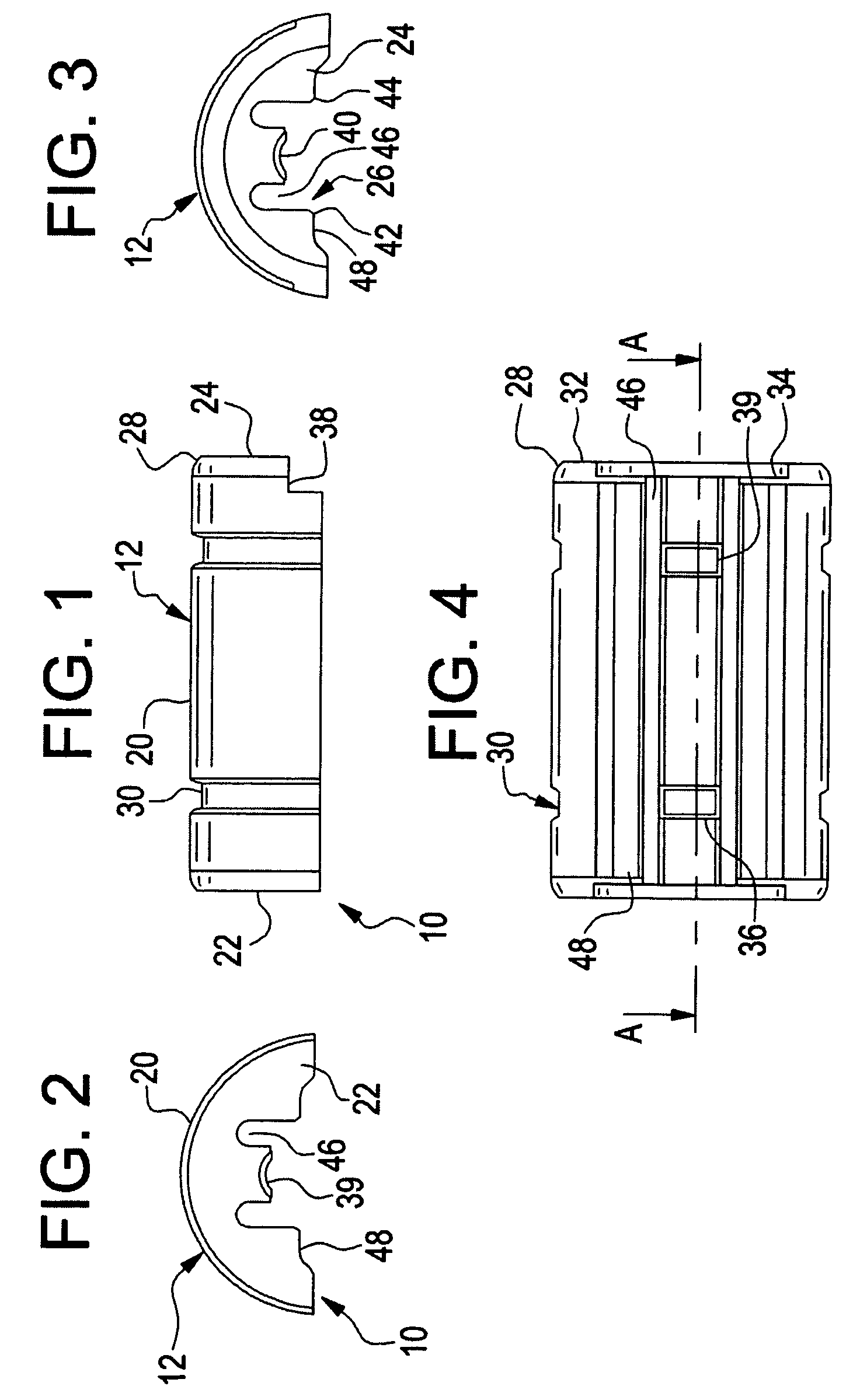
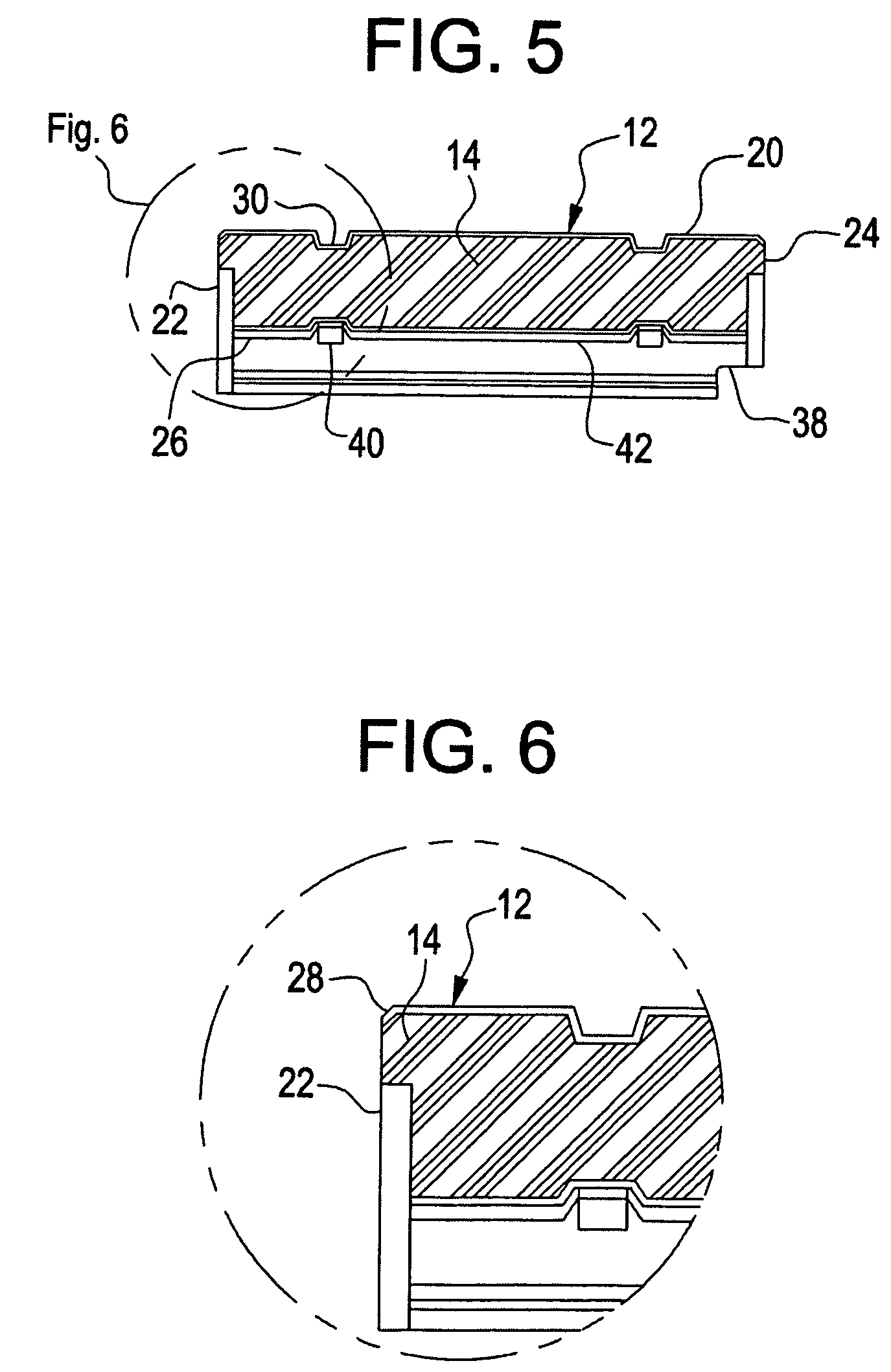
[0038]FIGS. 1-6 show a drilling riser buoyancy half 10 of the new invention. A tough plastic outer shell 12 is filled with buoyant material 14 which may be closed cell foam or a syntactic foam solid core.

[0039]The plastic shell 12 extends around the outside 20, ends 22, 24 and inside 26 of the half.

[0040]Grooves 30 are formed in the outside of the covers 10 to receive securing bands. Ends 22, 24 are tapered 28 to provide strengthened abutting surfaces 32 of the covers. Cavities 34 are formed in ends 22, 24 to receive auxiliary line clamps previously positioned on a drilling riser. Grooves 36 provide access for flexible resilient pads39. Ends 22 or 24 have steps 38 which, when juxtaposed, provide access for clamps.

[0041]Insides 26 of the cover halves 10 have short riser pipe configured surfaces 40, 42, 44 for positioning around the drilling riser pipe and provide recesses 46, 48 for holding auxiliary lines along the drilling risers, and permitting relative differential movements of e...


PUM


Abstract

Buoyancy modules for subsea riser pipes are made of syntactic foam solid cores covered with tough high density polyethylene shells. Inner surfaces have partial semi-cylindrical surfaces to fit the riser pipes. Internal radial grooves hold flexible contact pads. Recesses in the inner surfaces hold auxiliary lines. Flat surfaces between the inner and outer semi-cylindrical surfaces have complementary longitudinally extending semi-cylindrical grooves to position choke and kill lines. Grooves in the outer semi-cylindrical surfaces hold composite fiber tensioning straps directly outward from the flexible contact pads. Flat areas of the grooves hold tensioning hardware. Tensioning the straps grips the riser pipe with the pads and grips the choke and kill lines in the semi-circular grooves. Cavities in the ends allow the buoyancy module halves to be assembled on the riser pipe around clamps which hold the accompanying lines.

Description

[0001]This application claims the benefit of U.S. Provisional Application No. 61,000,476, filed Oct. 26, 2007, which is hereby incorporated by reference in its entirety.SUMMARY OF THE INVENTION[0002]Drilling riser buoyancy for subsea oil production has traditionally been produced using fiberglass skins. This invention used a polymer shell coating over a solid syntactic foam that is formed into the shape required and filled with the buoyant material. This method produces a product that is superior in both its performance, as well as, manufacturability.[0003]Buoyancy modules for subsea riser pipes are made of syntactic foam solid cores covered with tough high density polyethylene shells. Inner surfaces have partial semi-cylindrical surfaces to fit the riser pipes. Internal radial grooves hold flexible contact pads. Recesses in the inner surfaces hold auxiliary lines. Flat surfaces between the inner and outer semi-cylindrical surfaces have complementary longitudinally extending semi-cy...

Claims


Application Information

Patent Timeline
Patent Type & Authority Patents(United States)
IPC IPC(8): B63B22/00
CPCE21B17/012
Inventor COOK, TIMOTHY H.MAGUIRE, FREDERICKCAPOTOSTO, DAVID A.
Owner CUMING CORP
Why Eureka
Try Eureka