Polar modulator and wireless communication apparatus using the same

a wireless communication apparatus and modulator technology, applied in the field of modulation devices, can solve the problems of reducing operation efficiency, increasing size and cost, and especially consuming power for transmitting power to antennas, so as to improve power utilization efficiency, accurate amplitude modulated voltage, and accurate modulation

Inactive Publication Date: 2009-12-15
PANASONIC CORP
View PDF8 Cites 14 Cited by
  • Summary
  • Abstract
  • Description
  • Claims
  • Application Information

AI Technical Summary

Benefits of technology

[0045]According to a polar modulator of the present invention described above, the ACP included in the third modulated signal which is output from the power amplification section can be equal to or smaller than a predetermined value. Namely, the polar modulator can obtain a third modulated signal with the distortion component thereof suppressed by limiting the peak value of the second modulated signal, even if the amplifying element used in the power amplification section does not have linearity in a wide range. In addition, the polar modulator according to the present invention can prevent an unnecessary voltage from being supplied to the amplitude modulated voltage supply section and thus can improve the power utilization efficiency. The polar modulator according to the present invention can also prevent the transistor of each series regulator from being saturated. As a result, an accurate amplitude modulated voltage can be supplied to the power amplification section, and accurate modulation is made possible. A wireless communication apparatus, by using the polar modulator according to the present invention in a transmission section thereof, can be reduced in size and cost.
[0046]As described above, the present invention provides a polar modulator for improving the power utilization efficiency and / or enlarging the dynamic range, and a wireless communication apparatus using the same.

Problems solved by technology

A power amplification section for amplifying a high frequency signal and supplying transmission power to an antenna especially consumes a large amount of power.
However, a multi-mode wireless communication terminal produced based on the conventional technology inevitably includes a larger number of components, especially in the wireless section, and is increased in size and cost.
However, such a step generally reduces the operation efficiency.
However, when, for example, one polar modulator is commonly used for the GSM system and the UMTS, the size of the power amplifier cannot be reduced.
However, when a plurality of modulation systems are usable, such uniformization of the amplitude of the amplitude signal may result in the dynamic range being not securely obtained.
As described above, the conventional technologies are not sufficient in increasing the power utilization efficiency and / or enlarging the dynamic range.
Especially when a plurality of modulation systems are usable, for example, in a multi-mode operation, it is difficult to increase the power utilization efficiency and / or to enlarge the dynamic range with the conventional technologies.

Method used


Image

  • Polar modulator and wireless communication apparatus using the same
  • Polar modulator and wireless communication apparatus using the same
  • Polar modulator and wireless communication apparatus using the same

Examples


first embodiment

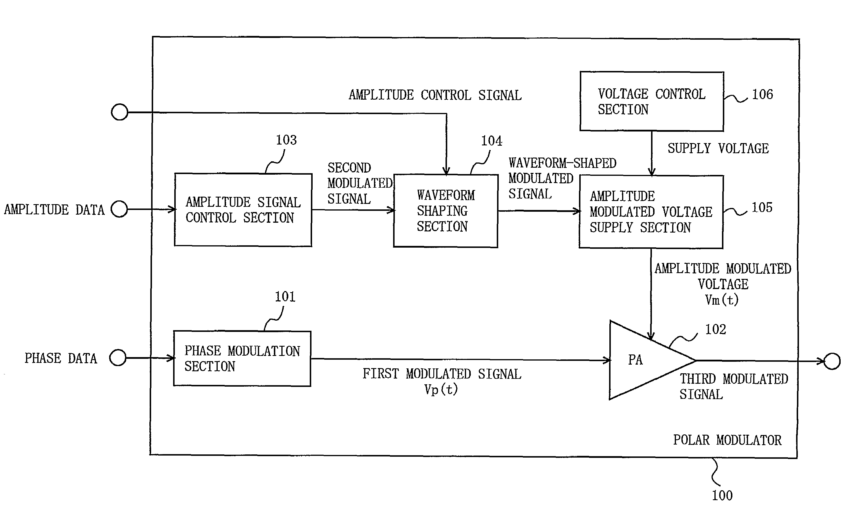
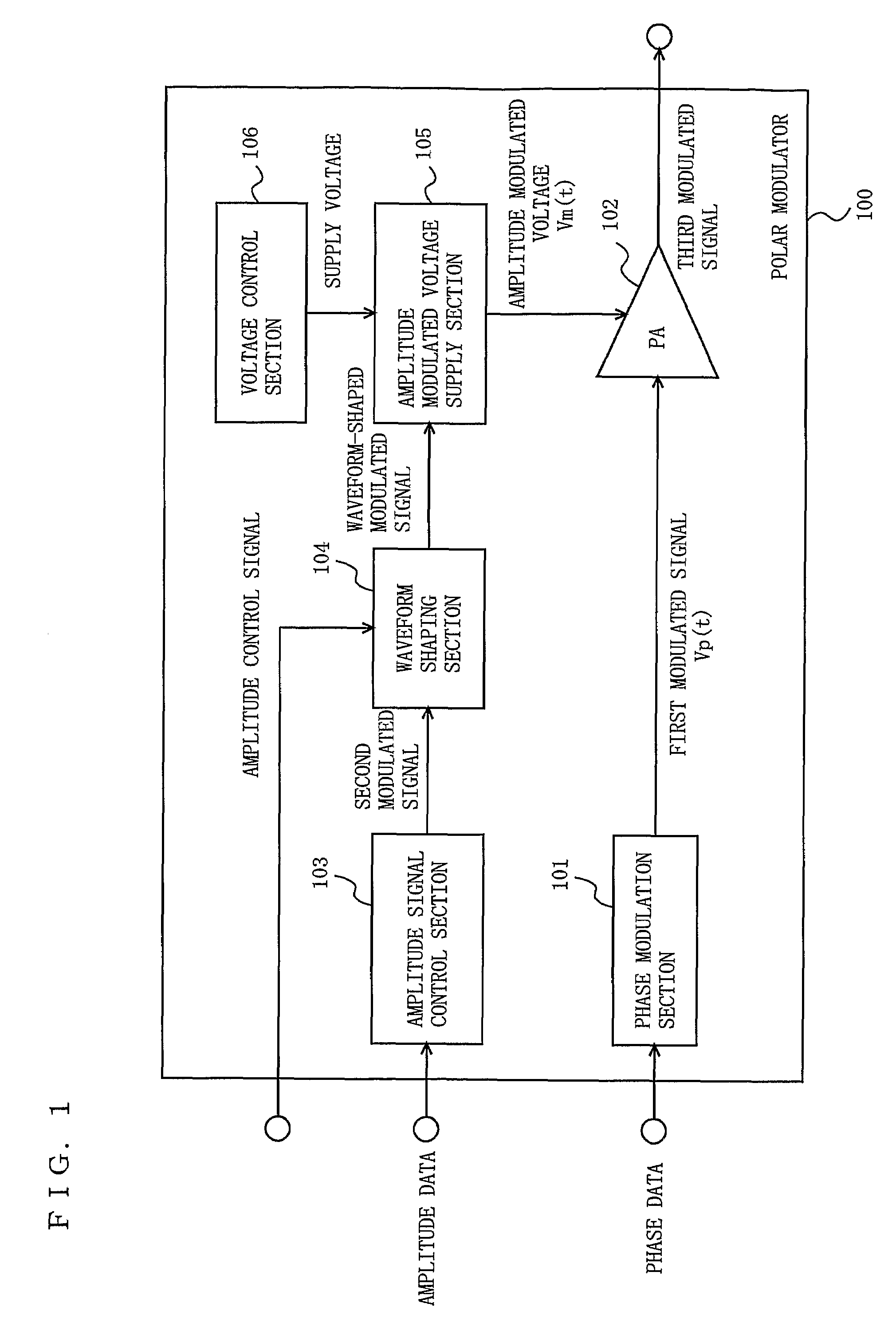
[0078]FIG. 1 is a block diagram showing a functional structure of a polar modulator 100 according to a first embodiment of the present invention. As shown in FIG. 1, the polar modulator 100 includes a phase modulation section 101, a power amplification section 102, an amplitude signal control section 103, a waveform shaping section 104, an amplitude modulated voltage supply section 105, and a voltage control section 106.

[0079]A baseband section (not shown in FIG. 1) decomposes a baseband signal into amplitude data (I) and phase data (Q). When, for example, a QPSK (Quadrature-Phase Shift Keying) signal is used as a baseband signal, the baseband section decomposes the QPSK signal into amplitude data and phase data. The amplitude data is input to the amplitude signal control section 103. The phase data is input to the phase modulation section 101.

[0080]The phase modulation section 101 generates a first modulated signal Vp(t) including phase information based on the phase data, and outp...

second embodiment

[0125]FIG. 9 is a block diagram showing a functional structure of a polar modulator 200 according to a second embodiment of the present invention. In FIG. 9, elements having substantially identical functions to those of the polar modulator 100 shown in FIG. 1 bear identical reference numerals thereto, and descriptions thereof will be omitted. The polar modulator 200 includes a phase modulation section 101, a power amplification section 102, an amplitude signal control section 103, a waveform shaping section 204, an amplitude modulated voltage supply section 205, a voltage control section 206, and a switch section 207.

[0126]The voltage control section 206 includes first through third DC power supplies 206a, 206b and 206c capable of outputting a plurality of different supply voltages from one another.

[0127]The amplitude modulated voltage supply section 205 includes first through third series regulators 205a, 205b and 205c respectively provided in correspondence with the first through ...

third embodiment

[0132]FIG. 10 is a block diagram showing a functional structure of a polar modulator 300 according to a third embodiment of the present invention. In FIG. 10, elements having substantially identical functions to those of the polar modulator 100 shown in FIG. 1 bear identical reference numerals thereto, and descriptions thereof will be omitted. The polar modulator 300 includes a phase modulation section 101, a power amplification section 102, an amplitude signal control section 303, an amplitude modulated voltage supply section 305, and a voltage control section 306.

[0133]The amplitude signal control section 303 has substantially the same function as that of the amplitude signal control section 103 in the first embodiment except for inputting the second modulated signal to the voltage control section 306 and the amplitude modulated voltage supply section 305.

[0134]The amplitude modulated voltage supply section 305 includes a transistor. The amplitude modulated voltage supply section ...


PUM


Abstract

A phase modulation section (101) generates a first modulated signal including phase information. An amplitude signal control section (103) generates a second modulated signal including amplitude information. A waveform shaping section (104), when an amplitude of the second modulated signal is larger than a regulated value generates a waveform-shaped modulated signal. An amplitude modulated voltage supply section (105) amplifies the waveform-shaped modulated signal based on the supply voltage from a voltage control section (106) and supplies the amplified signal to a power amplification section (102). The power amplification section (102) amplifies the first modulated signal based on the amplitude modulated voltage, and outputs the resultant signal. The waveform shaping section (104) adjusts the regulated value in accordance with a factor for changing a distorted power generated by the power amplification section (102), such that an ACP generated by the power amplification section (102) becomes a first predetermined value or smaller.

Description

TECHNICAL FIELD[0001]The present invention relates to a modulation device, and more particularly to a polar modulator and a wireless communication apparatus using the same.BACKGROUND ART[0002]Cellular phones are desired to be usable for a long period of time with a limited amount of battery capacity. A power amplification section for amplifying a high frequency signal and supplying transmission power to an antenna especially consumes a large amount of power. Therefore, it is important to improve the efficiency of the power amplification section.[0003]Various communication systems have become widely used in the world, and a multi-mode wireless communication terminal which is usable with a plurality of communication systems is desired. However, a multi-mode wireless communication terminal produced based on the conventional technology inevitably includes a larger number of components, especially in the wireless section, and is increased in size and cost. In order to realize a multi-mod...

Claims


Application Information

Patent Timeline
Patent Type & Authority Patents(United States)
IPC IPC(8): H04K1/02
CPCH03C5/00H04L27/367H04L27/361H04L27/2623
Inventor MORIMOTO, SHIGERUMATSUURA, TORUADACHI, HISASHI
Owner PANASONIC CORP
Why Eureka
Try Eureka