Multiple pass economizer and method for SCR temperature control

a technology of economizer and economizer, which is applied in the direction of machine/engine, steam generation using hot heat carriers, lighting and heating apparatus, etc., can solve the problems of increasing the gas outlet temperature of the economizer, reducing the total gas side heat transfer of the economizer, etc., to reduce the heat transfer, increase the outlet temperature of the flue gas passing, and reduce the effect of water flow

Inactive Publication Date: 2009-12-29
THE BABCOCK & WILCOX CO
View PDF13 Cites 18 Cited by
  • Summary
  • Abstract
  • Description
  • Claims
  • Application Information

AI Technical Summary

Benefits of technology

[0008]It is an object of the present invention to provide a system and method for increasing the outlet temperature of flue gas passing through the economizer by reducing the water flow in selected tubes and / or sections of the economizer without the need to divert feedwater away from the economizer. When these selected tubes or sections are reduced in flow, the remaining sections or tubes in the economizer are overflowed so that the total flow is maintained through the economizer. To increase the economizer gas outlet temperature, a certain percentage of the tubes in the economizer will have their heat transfer reduced by decreasing the flow through these tubes. The increase in water flow in the remaining tubes has a minimal effect on the heat transfer of the remaining tubes, resulting in an overall decrease in the total gas side heat transfer of the economizer and as a result increases the gas outlet temperature from the economizer.
[0012]It is a further object of the present invention to provide a method of maintaining a gas stream being directed into a downstream device such as an SCR assembly within a desired temperature range or at a desired (e.g., optimal) temperature, the SCR assembly being located downstream of and in fluid communication with an economizer, the method comprising disposing, within the economizer, at least two tubular configurations in a cross and or counter-current heat exchange relationship with the flow path of the gas stream, the economizer having a flue inlet and a flue outlet, each tubular configuration comprises a feed water inlet and a feed water outlet, the outlet of both tubular configurations being attached to an outlet header and the inlet of each tubular configuration being attached to a separate inlet header, monitoring the gas temperature at the flue inlet or flue outlet, the feedwater temperature at the feedwater inlet and outlet, and the flow of feedwater through the economizer, controlling the flow of feedwater conveyed through each tubular configuration, based on the measured temperatures and flow, to provide the tubular configurations with a combined heat transfer capacity that is effective to maintain the gas temperature at the desired level, wherein the heat transfer capacity of the tubular configurations is decreased by increasing the flow of feedwater through at least one of the tubular configurations and by reducing the flow of feedwater through the other tubular configurations.
[0013]While the present invention is particularly suited to maintaining a desired flue gas temperature entering a downstream SCR device, it will be appreciated that the invention may be used to maintain a desired gas temperature which may required by other types of downstream devices, and for other purposes. One type of downstream device could be an air heater which typically uses the heat in the flue gas leaving the steam generator to heat the incoming air for combustion. In some cases it is desirable to control the flue gas temperature entering the air heater within a desired range or at a desired temperature above the acid dew point temperature, such as during low load operation, to reduce the possibility of condensation occurring which could form acidic compounds which could lead to corrosion of the air heater. Other types of downstream devices include various types of pollution control equipment; e.g., particulate removal devices such as electrostatic precipitators or fabric filters, and flue gas desulfurization devices such as wet or dry flue gas desulfurization equipment.

Problems solved by technology

The increase in water flow in the remaining tubes has a minimal effect on the heat transfer of the remaining tubes, resulting in an overall decrease in the total gas side heat transfer of the economizer and as a result increases the gas outlet temperature from the economizer.

Method used


Image

  • Multiple pass economizer and method for SCR temperature control
  • Multiple pass economizer and method for SCR temperature control
  • Multiple pass economizer and method for SCR temperature control

Examples


Embodiment Construction

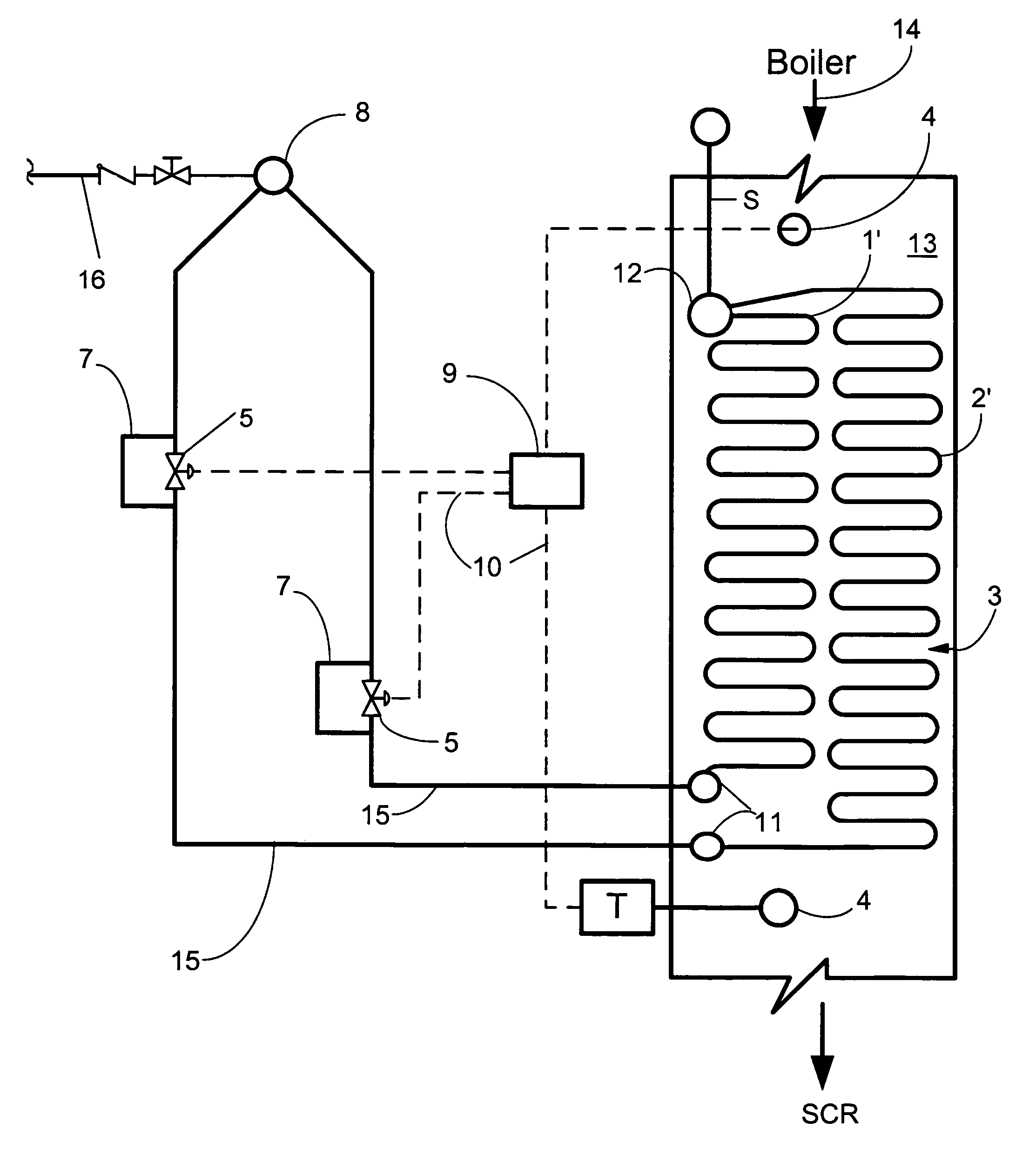
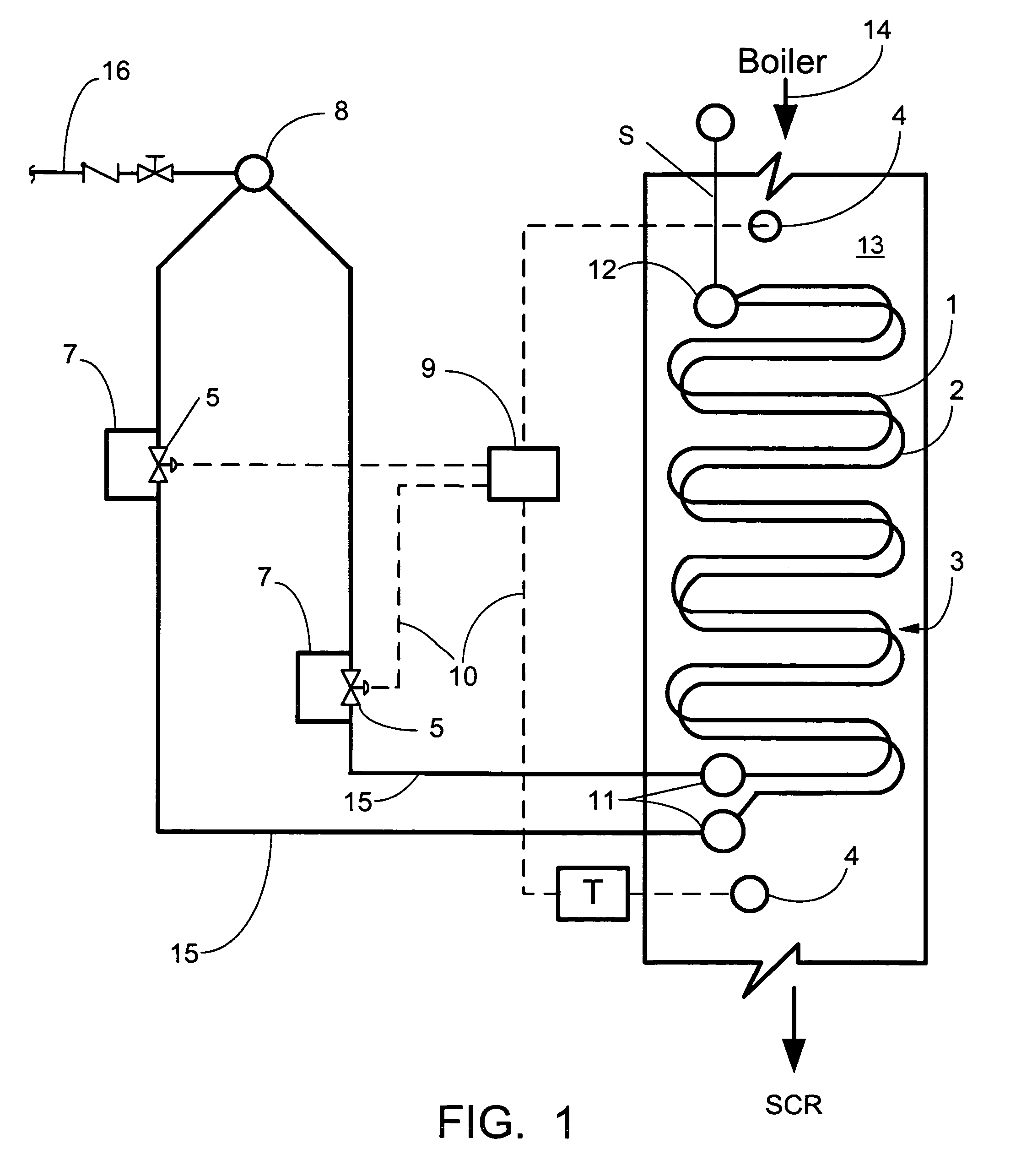
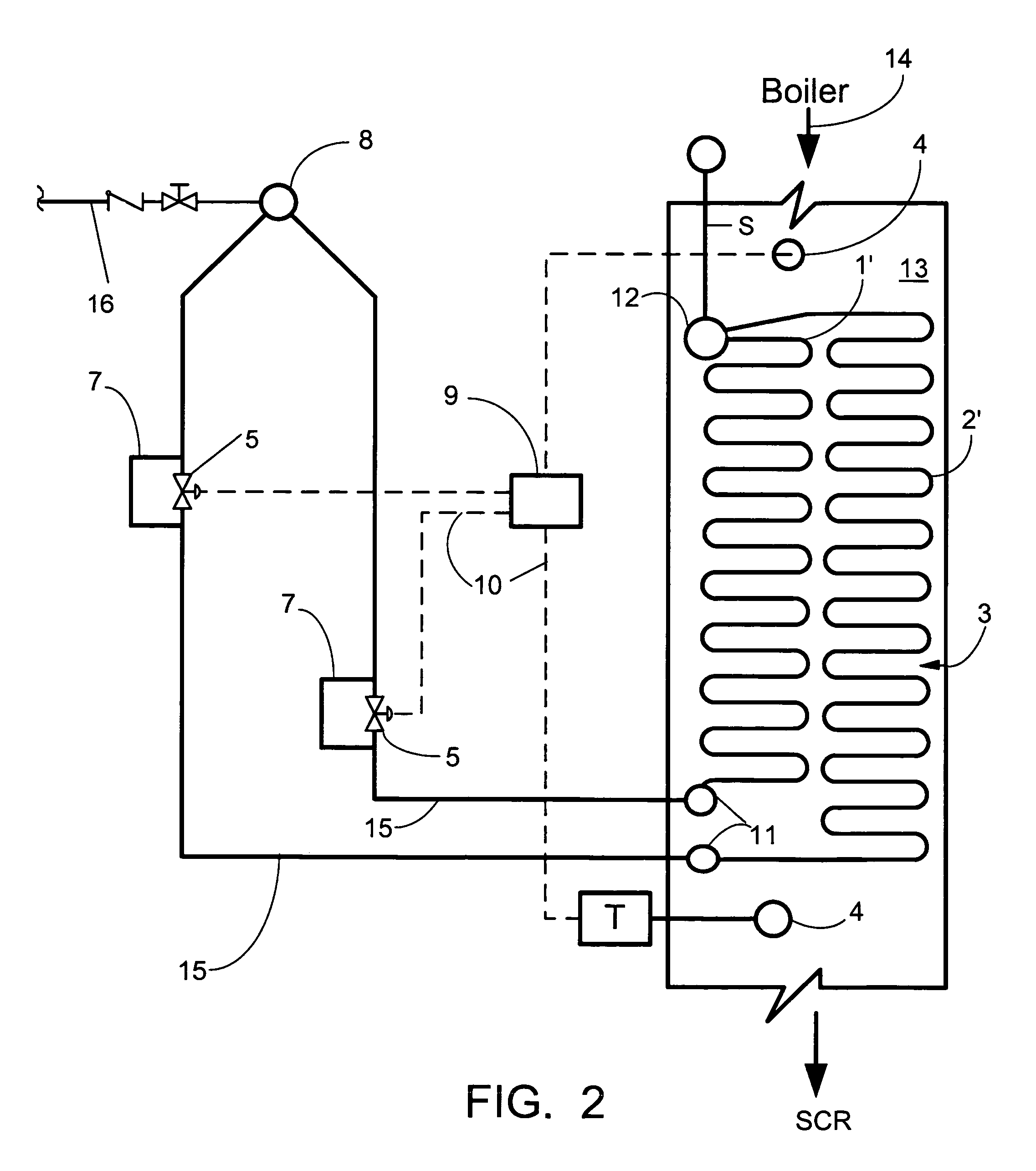
[0025]Referring now to the drawings, in which like reference numerals are used to refer to the same or functionally similar elements, FIG. 1 shows an economizer 3 for receiving flue gas generated by a boiler (not shown), located upstream of and in fluid communication with the economizer 3. As used in the present application and as is known to those skilled in the art, the term boiler is used herein to broadly refer to apparatus used for generating steam and may include both drum-type boilers and those of the once-through type. For a general description of such types of boilers or steam generators, the reader is referred to the aforementioned STEAM 41st reference, particularly the Introduction and Selected color plates, and Chapters 19, 20, and 26, the text of which is hereby incorporated by reference as though fully set forth herein. The economizer 3 includes a flue inlet and a flue outlet, and is located in a convection pass 13 upstream of and in fluid communication with a Selectiv...


PUM


Abstract

A control system for maintaining a desired heat exchanger outlet flue gas temperature across a range of boiler loads. The heat exchanger includes a plurality of tubular configurations in heat exchange contact with the flue gas with each tubular configuration having a separate feedwater inlet. Flue gas temperature control is achieved by modulating the feedwater flow rates through the tubular configurations. In a system having two tubular configurations, the overall heat transfer capacity of the heat exchanger may be reduced to maintain the desired heat exchanger outlet flue gas temperature by reducing feedwater flow through one tubular configuration and overflowing the other, while maintaining the total flow of feedwater through the heat exchanger substantially constant.

Description

CROSS REFERENCE TO RELATED APPLICATION[0001]The present invention is a continuation-in-part of U.S. application Ser. No. 11 / 430,761 filed May 9, 2006.FIELD AND BACKGROUND OF THE INVENTION[0002]The present invention relates generally to the field of Selective Catalyst Reactor (SCR) temperature control and in particular to a system and method for maintaining the combustion or flue gas entering the SCR system at or above the optimal catalytic reaction temperature, even when operating the boiler at reduced loads.[0003]In operating a boiler with a Selective Catalyst Reactor (SCR) system, the effectiveness of the SCR is dependant upon the flue gas temperature entering the catalyst reactor. Most can operate within a temperature range of about 450 degrees F. to about 840 degrees F. Optimum performance may typically occur between about 570 degrees F. to about 750 degrees F. Typically, the desired gas temperature entering the SCR is about 580 degrees F. or greater. At a temperature of about 5...

Claims


Application Information

Patent Timeline
Patent Type & Authority Patents(United States)
IPC IPC(8): F22G1/02
CPCF22D1/12
Inventor ALBRECHT, MELVIN JOHNBLOSS, JAMES S.FRASCELLO, STEPHEN V.MCGREGOR, MONTE J.
Owner THE BABCOCK & WILCOX CO
Why Eureka
Try Eureka