
Film forming apparatus, manufacturing management system and method of manufacturing semiconductor devices

a film forming apparatus and manufacturing management system technology, applied in the direction of liquid/solution decomposition chemical coating, coating, instruments, etc., can solve the problems of affecting the quality assurance period of the chemical solution remaining in the pipeline within the film forming apparatus may have expired, and the quality assurance period of the chemical solution may have expired

Inactive Publication Date: 2009-12-29
KK TOSHIBA
View PDF13 Cites 14 Cited by
  • Summary
  • Abstract
  • Description
  • Claims
  • Application Information

AI Technical Summary

Benefits of technology

The present invention provides a film forming apparatus, method, and manufacturing management system that can determine the quality of a chemical solution used in the film formation process. This is done by creating correlation data from data related to the properties of the chemical solution, such as storage temperature and pressure applied during loading. The system can then determine if the chemical solution is of expected quality and allocate product lots to external film forming apparatuses based on the determined quality. The technical effects include improved quality control and efficient allocation of resources for film formation.

Problems solved by technology

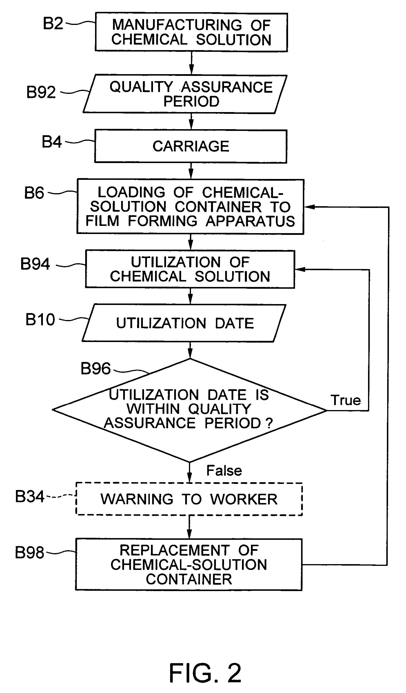
In the case where the amount of a chemical solution to be used is large enough compared to the capacity of the container of the chemical solution, and where the entire chemical solution in one container is quickly consumed, it is very seldom that the quality assurance period of the chemical solution raises a problem.
However, in the case where devices to be manufactured are a wide variety of products in small quantities, whereby the amounts of chemical solutions to be used are little, where the production line for the devices are halted for some reasons, or where any event occurs that halts for a long time processing in film forming processes for the devices, the quality assurance periods of the chemical solutions may expire.
Among the foregoing problems, the cases where a chemical-solution container is kept being connected with a manufacturing system regardless of the expiration of the quality assurance period include the following two cases: In the first place, relying on a periodical and manual check may cause chemical solutions whose quality assurance periods have expired to be kept being loaded, by a worker's false recognition or by false instructions.
In addition, even though the quality assurance period of a chemical solution in a chemical-solution container has not expired, the quality assurance period of the chemical solution remaining in the pipeline within a film forming apparatus may have expired.
Even though such a rule is adopted in which, after the replacement of the chemical-solution container, the entire chemical solution in the pipeline is disposed of, the false recognition by a worker may make the disposal insufficient.
As discussed above, existing technology may cause the possibility of utilizing chemical solutions whose quality assurance periods have expired.
Moreover, even when quality assurance periods are still valid, if storage conditions for chemical solutions, in particular, temperature management conditions, from manufacturing of the chemical solutions to loading them in a film forming apparatus are inappropriate, the deterioration of the chemical solutions develops.
Therefore, a case exists in which management by means of a quality assurance period only is insufficient.
Still moreover, even though temperature management during the time from manufacturing of a chemical solution to loading it in a film forming apparatus is appropriate, if the temperature of the pipeline within the film forming apparatus is inappropriate, the deterioration of the chemical solutions develops in the pipeline, even when the quality assurance period of the chemical solution has not expired.
Meanwhile, when a chemical solution to be utilized is very expensive, the reduction of its amount to be used is effective to reduction of cost in manufacturing devices.

Method used


Image

  • Film forming apparatus, manufacturing management system and method of manufacturing semiconductor devices
  • Film forming apparatus, manufacturing management system and method of manufacturing semiconductor devices
  • Film forming apparatus, manufacturing management system and method of manufacturing semiconductor devices

Examples


embodiment 1

(1) Film Forming Apparatus

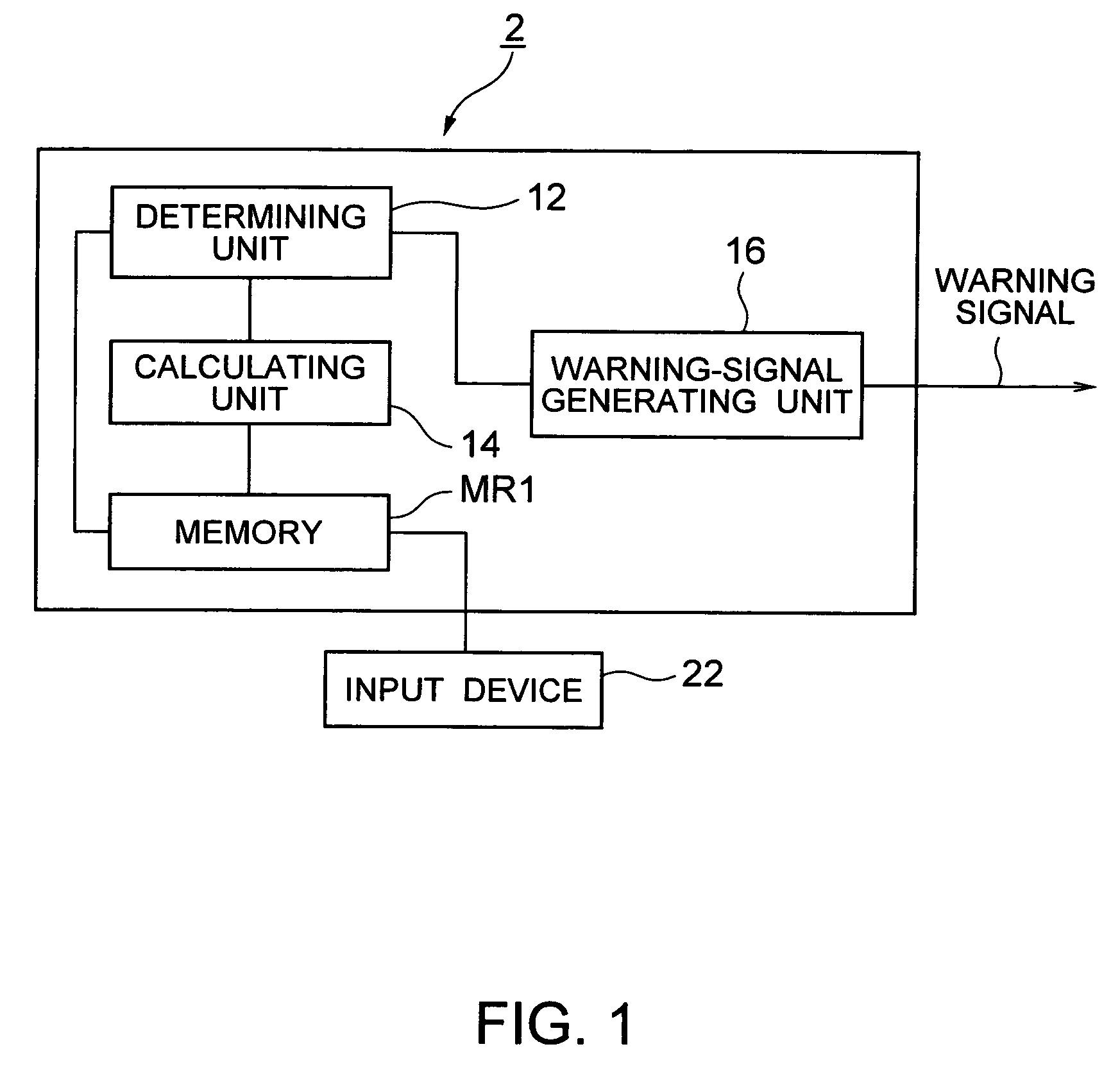
[0036]FIG. 1 is a block diagram illustrating the schematic configuration of a film forming apparatus according to Embodiment 1. A film forming apparatus 2 illustrated in FIG. 2 is provided with an input device 22, a memory MR1, a calculating unit 14, a determining unit 12, and a warning-signal generating unit 16. The input device 22 inputs a temperature history of a chemical solution to be utilized for forming a film or predetermined calculation parameters for calculation. The temperature history of a chemical solution, in Embodiment 1, for example, corresponds to data related to properties of the chemical solution. The memory MR1 stores the temperature history inputted, the calculation parameters inputted, and threshold-value information described later. In addition, as described later, the calculating unit 14 may in some cases calculate a threshold value by utilizing data in the memory MR1. The memory MR1 can also store in the form of a recipe file a seri...

embodiment 2

(4) Embodiment 2

[0060]Next, Embodiment 2 of the present invention will be discussed, referring to FIG. 5.

[0061]In the present embodiment, unlike Embodiment 1 described above, the discussion will be made by dealing with a case where a chemical solution to be used is contained in a container that discharges the chemical solution by means of pressure-applying gas (e.g., nitrogen or basic-substance-removed air).

[0062]The film forming apparatus 2 illustrated in FIG. 1 can be utilized also in the present embodiment. As a predetermined calculation that is implemented by the calculating unit 14 and that is to describe the change with time in the properties of a chemical solution, the calculation utilizing the quadrature by parts of temperature and elapsed time that has been utilized in Embodiment 1, as the simplest method, is employed.

[0063]In the case of a chemical-solution bottle conceived in Embodiment 2, a photoresist solution deteriorates its performance, depending on the elapsed time ...

embodiment 3

(5) Embodiment 3

[0067]Next, Embodiment 3 of the present invention will be discussed, referring to FIGS. 6 and 7.

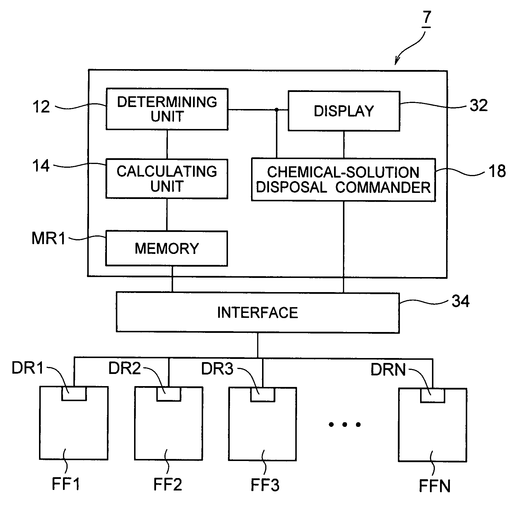
[0068]FIG. 6 is a block diagram illustrating the schematic configuration of a film forming apparatus according to Embodiment 3. As is clear from the comparison to FIG. 1, a film forming apparatus 4 illustrated in FIG. 6 is provided with a chemical-solution disposal commander 18, in addition to the configuration in FIG. 1. The rest of the configuration of the film forming apparatus 4 is substantially the same as that of the film forming apparatus 2 of Embodiment 1.

[0069]In the film forming apparatus 4 illustrated in FIG. 6, if the result of a determination by the determining unit 12 is false, the chemical-solution disposal commander 18 creates a disposal command signal and sends it to an unillustrated valve opening / closing device; in consequence, the chemical solution remaining within the path from the chemical-solution outlet (refer to FIG. 8) of a chemical-solution contai...


PUM

PropertyMeasurementUnit
temperatureaaaaaaaaaa
pressureaaaaaaaaaa

Abstract

A film forming apparatus which forms a film on a substrate by utilizing a chemical solution, including: a correlation data creating unit which creates a correlation data that is related to the quality of a chemical solution, from data that is related to the properties of the chemical solution including at least one of data on storage temperature for the chemical solution to be loaded and data on pressure applied to the chemical solution to be loaded; and a determining unit which determines whether or not the chemical solution holds expected quality thereof on the bases of the correlation data.

Description

CROSS REFERENCE TO RELATED APPLICATION[0001]This application claims benefit of priority under 35 USC §119 to Japanese Patent Application No. 2004-138378, filed on May 7, 2004, the contents of which are incorporated by reference herein.BACKGROUND OF THE INVENTION[0002]1. Field of the Invention[0003]The present invention relates to a film forming apparatuses, a manufacturing management system, and a method of manufacturing semiconductor devices.[0004]2. Related Background Art[0005]In manufacturing of devices, the formation of a film, such as a SOG (Spin on Glass) film as an insulating layer, an antireflection film used in lithography processes, and a photoresist film, using a chemical solution is being employed in many processes. Most of these chemical solutions deteriorate as time passes; therefore, in general, in order to maintain predetermined performances, or in some cases, in order to ensure safety in manufacturing, manufacturers of such chemical solutions set chemical-solution s...

Claims


Application Information

Patent Timeline
Patent Type & Authority Patents(United States)
IPC IPC(8): B05C5/02B05D1/26B05C11/00H01L21/31B05D3/00H01L21/316
CPCH01L21/316H01L21/02282C23C18/1628C23C18/02
Inventor KAWAMURA, DAISUKE
Owner KK TOSHIBA
Learn More