Liquid-jet head, method of manufacturing the same, and liquid-jet apparatus

a liquid-jet head and liquid-jet technology, applied in printing and other directions, can solve the problems of difficult high-density arrangement, difficult manufacturing process, and difficult piezoelectric layer dielectric breakdown, and achieve the effect of easy formation

Active Publication Date: 2010-01-05
SEIKO EPSON CORP
View PDF2 Cites 6 Cited by
  • Summary
  • Abstract
  • Description
  • Claims
  • Application Information

AI Technical Summary

Benefits of technology

[0017]According to the first aspect, by providing the thin-thickness portions in the lower electrode, electric field strength can be reduced in near-end portions of the plural piezoelectric elements, whereby amounts of distortion of piezoelectric elements can be reduced in these near-end portions in comparison to those in a central portion of the piezoelectric elements. As a result, durability of the liquid-jet head when it is driven can be enhanced.
[0029]According to the seventh aspect, while the notch portions can be easily formed in the lower electrode, alignment of the notch portions with the piezoelectric layer and the upper electrode becomes unnecessary. Thereby, it becomes possible to make an arrangement density of piezoelectric elements high-density.

Problems solved by technology

On the other hand, this type requires: a difficult process of cutting the piezoelectric elements into a comb-tooth shape while aligning the piezoelectric elements with arrangement pitches of the nozzle orifices; and an operation of positioning and fixing the cut piezoelectric elements with the pressure generating chambers.
Accordingly, this type has a problem that a manufacturing process is complicated.
Nevertheless, a certain area is required for the use of flexure vibration, whereby this type has a problem that high-density arrangement is difficult.
However, this recoding head has a problem that an electric discharge occurs between each of the upper electrodes and the lower electrode, and eventually causes dielectric breakdown of the piezoelectric layer, because electric field concentration occurs in end portions of the piezoelectric layers and the upper electrodes in a lead-out side thereof.
In such a configuration where the narrow-width portion is thus formed in the lower electrode, the narrow-width portion has to be formed by patterning when the lower electrode is patterned, whereby pattern formation for this configuration is complicated.
In addition, alignment of the narrow-width portion with the piezoelectric layer and the upper electrode is required, whereby, if an arrangement density of the piezoelectric elements becomes high-density, there arises a problem that the alignment is difficult.
Note that, obviously, the aforementioned problems exist not only with an ink-jet recording head, but also with other liquid-jet heads which eject liquid other than ink in like manner.

Method used


Image

  • Liquid-jet head, method of manufacturing the same, and liquid-jet apparatus
  • Liquid-jet head, method of manufacturing the same, and liquid-jet apparatus
  • Liquid-jet head, method of manufacturing the same, and liquid-jet apparatus

Examples


embodiment 1

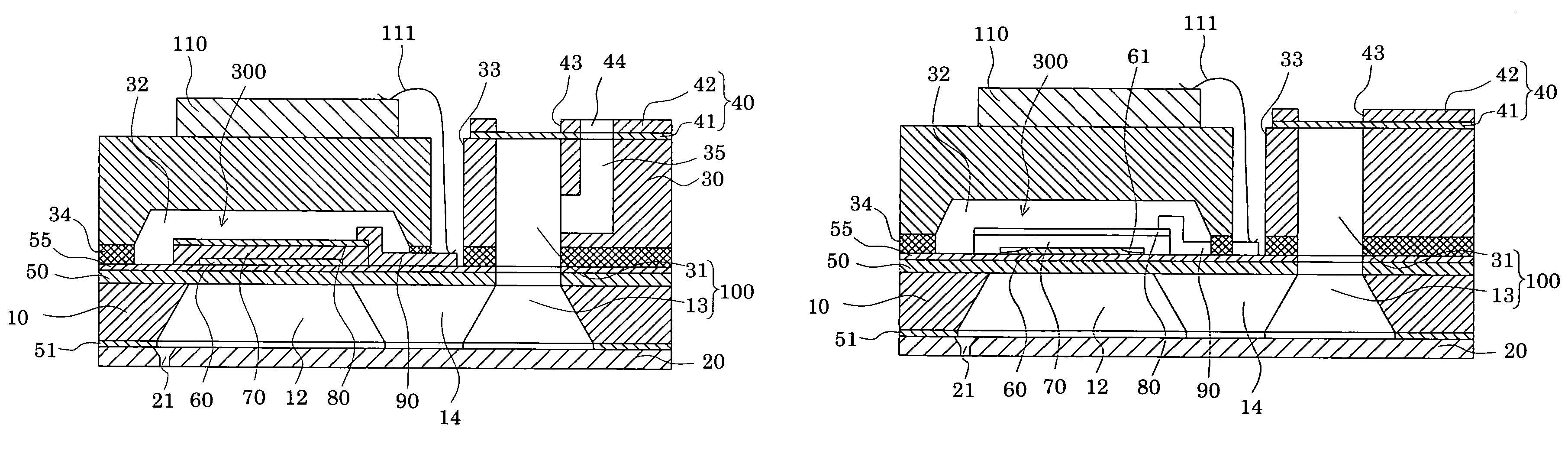
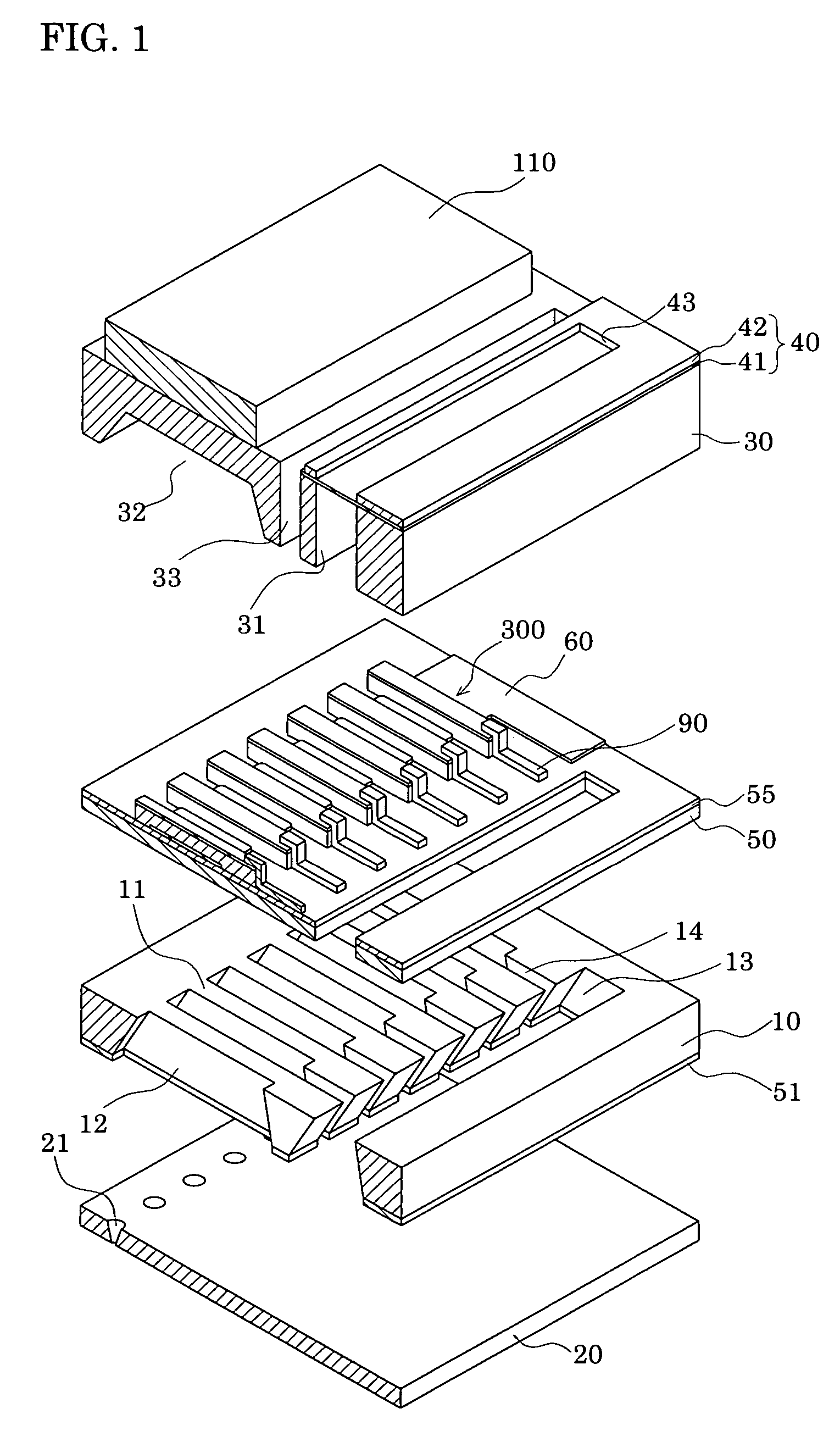
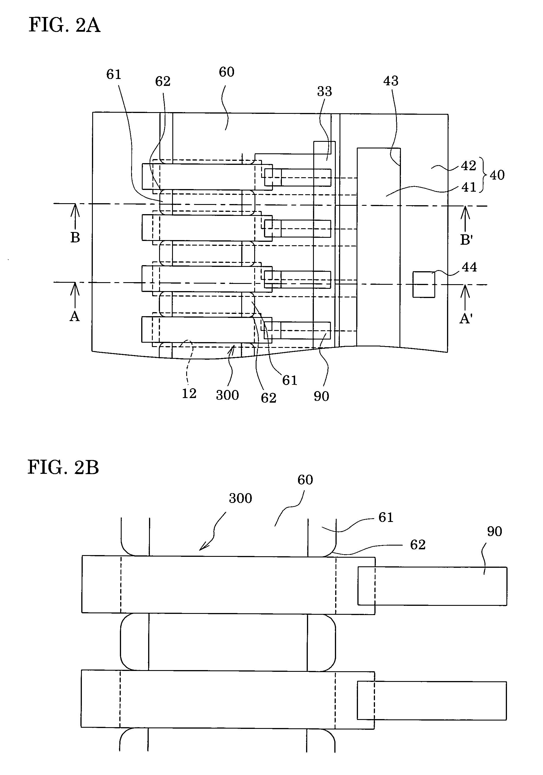
[0037]FIG. 1 is an exploded perspective view of an ink-jet recoding head according to Embodiment 1 of the invention, FIGS. 2A and 2B are plan views of main portions of the ink-jet recoding head, and FIGS. 3A and 3B are cross-sectional views taken along an A-A′ line and a B-B′ line, respectively, in FIG. 2A.

[0038]As illustrated, a passage-forming substrate 10 is made of a single crystal silicon substrate of the (110) plane orientation in this embodiment. On both upper and lower surfaces of the passage-forming substrate 10, there is formed an elastic film 50 in a 0.5 to 2 μm thickness made of silicon dioxide which has been previously formed by thermal oxidation.

[0039]In the passage-forming substrate 10, by applying anisotropic etching thereto from the other surfaces thereof, a plurality of pressure generating chambers 12 partitioned by a plurality of compartment walls 11 are provided so as to be arrayed in a line. Additionally, in the passage-forming substrate 10, a communicating port...


PUM


Abstract

Provided are, a liquid-jet head capable of enhancing durability thereof when it is driven, and of making an arrangement density of piezoelectric elements high-density, a method of manufacturing the same, and a liquid-jet apparatus. The liquid-jet head includes: piezoelectric elements which are provided on a passage-forming substrate with a vibration plate interposed therebetween, and are respectively configured of a lower electrode, piezoelectric layers and upper electrodes, the passage-forming substrate having pressure generating chambers, which communicate with nozzle orifices for ejecting liquid droplets, formed therein, in which, while the lower electrode is continuously provided across plural piezoelectric elements, near-end portions of the lower electrode at least in regions of the lower electrode between adjacent ones of the piezoelectric elements are formed into thin-thickness portions thinner than portions of the lower electrode in other regions of the lower electrode.

Description

[0001]The entire disclosure of Japanese Patent Application No. 2005-187280 filed Jun. 27, 2005 is expressly incorporated by reference herein.BACKGROUND[0002]1. Technical Field[0003]The present invention relates to a liquid-jet head which ejects liquid from nozzle orifices, a method of manufacturing the same, and a liquid-jet apparatus. Particularly, the invention relates to: an ink-jet recording head, in which a part of pressure generating chambers communicating with nozzle orifices ejecting ink droplets is constructed of a vibration plate, piezoelectric elements are formed on a surface of this vibration plate, and displacement of the piezoelectric elements allows ink to be ejected; a method of manufacturing the same; and an ink-jet recording apparatus.[0004]2. Related Art[0005]As an inkjet recording head, in which a part of each of pressure generating chambers communicating with nozzle orifices ejecting ink droplets is constructed of a vibration plate, and this vibration plate is d...

Claims


Application Information

Patent Timeline
Patent Type & Authority Patents(United States)
IPC IPC(8): B41J2/045
CPCB41J2/14233B41J2/161B41J2/1623B41J2/1628B41J2/1635B41J2/1646B41J2002/14241B41J2002/14419B41J2002/14491
Inventor SHIMADA, MASATO
Owner SEIKO EPSON CORP
Why Eureka
Try Eureka