Vehicle with primary cruiser engine and auxiliary accelerator engine

a technology of auxiliary accelerator and cruiser engine, which is applied in the field of vehicles, can solve the problems of poor acceleration performance, complex hybrid vehicle structure, and high manufacturing and maintenance costs, and achieve the effects of improving acceleration performance, reducing production costs, and reducing production costs

Inactive Publication Date: 2010-01-05
BELLOSO GREGORIO M
View PDF5 Cites 21 Cited by
  • Summary
  • Abstract
  • Description
  • Claims
  • Application Information

AI Technical Summary

Benefits of technology

[0036]i) enabling said auxiliary accelerator engine to remai

Problems solved by technology

Hybrid vehicles are complex and expensive to manufacture and maintain due to the need for high amperage capacity batteries and associated control components.
One particular disadvantage of hybrid vehicles is that, when the charge of the batteries is exhausted, such as during prolonged uphill climbs, the vehicle suddenly becomes severely under-powered because the electric motor is then unable to supply the needed additional power, and the vehicle has to rely solely on the power supplied by its down-sized engine.
It is well known that by simply using a small displacement internal combustion engine in a vehicle instead of its standard engine, the vehicle will gain improved fuel efficiency, but will have poor acceleration performance.
The market, however, requires that the vehicle can accelerate from 0 to 60 MPH within 10 to 12 seconds, otherwise the vehicle will not sell.
So far, however, this approach has not had significant success in the market mainly due to difficulties in achieving optimum coordination of the engines.
Fuel savings through this solution, however, has been severely limited, mainly due to power losses associated with the continuing reciprocating motion of the components (pistons, con rods, etc.) within the deactivated cylinders.
One disadvantage of this system is the limited power capacity and speed range of current continuously variable ratio torque converters.
However, it does not improve power handling capacity.
This system is complex and is not readily adaptable for use in automotive vehicles, particularly for the specific purpose of improving fuel effici

Method used


Image

  • Vehicle with primary cruiser engine and auxiliary accelerator engine
  • Vehicle with primary cruiser engine and auxiliary accelerator engine
  • Vehicle with primary cruiser engine and auxiliary accelerator engine

Examples


Embodiment Construction

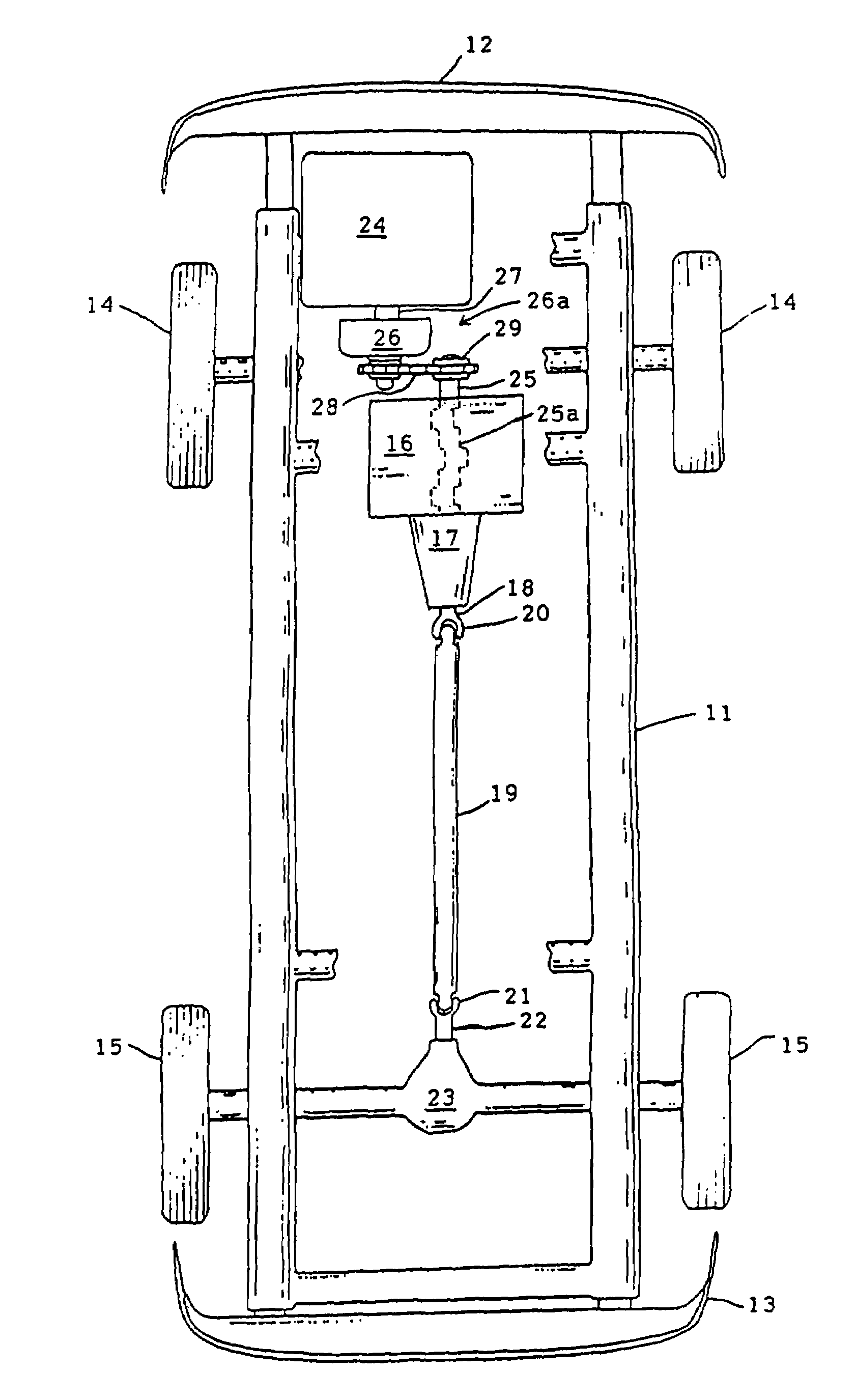
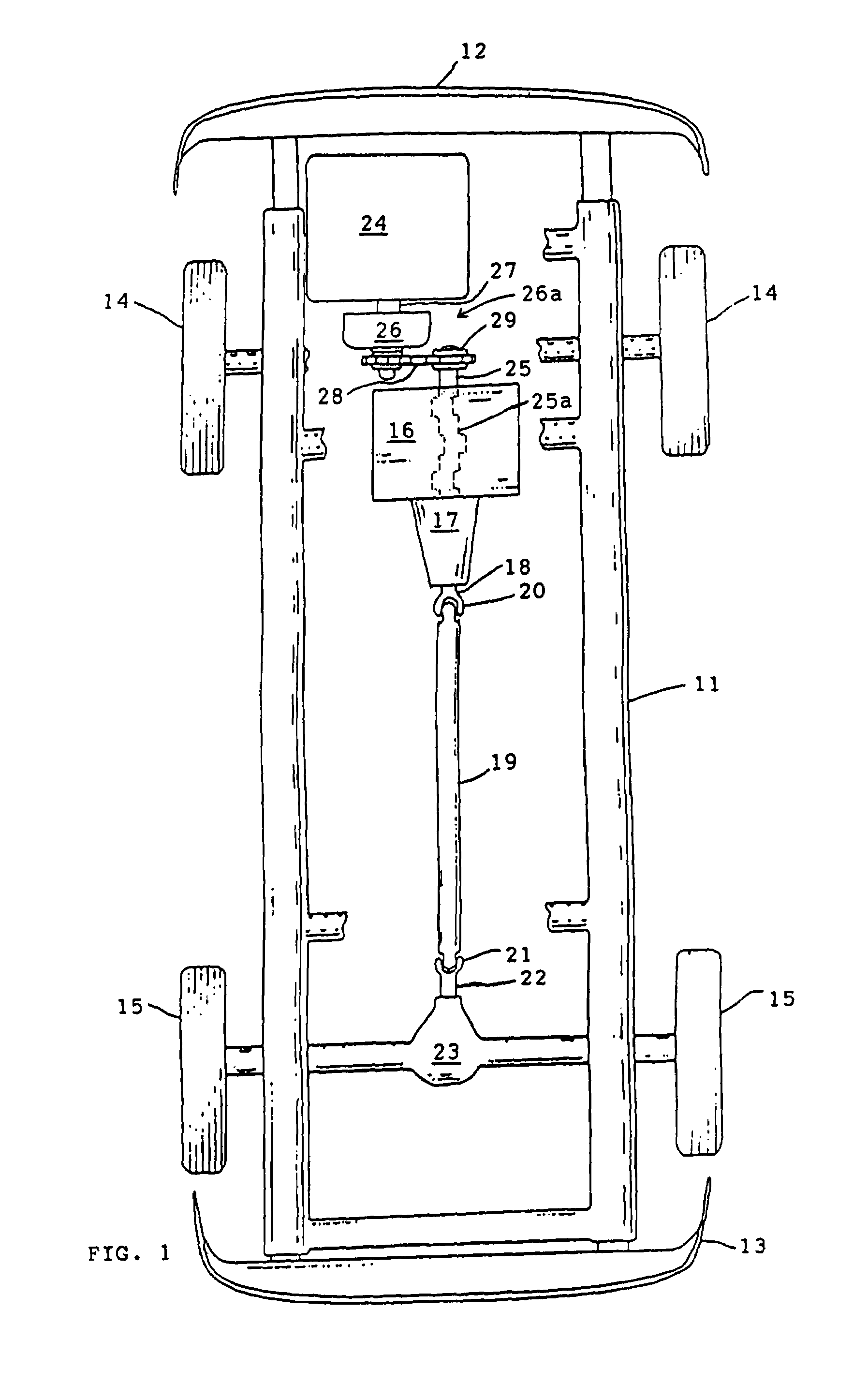
[0047]Referring now to the drawings wherein one character designates one part of the vehicle, FIG. 1 shows the vehicular chassis 11 connected to front bumper 12 and rear bumper 13, and supported by paired front wheels 14 and rear wheels 15.

[0048]A power train is shown comprised of primary “cruiser” engine 16 mounted on chassis 11 and coupled to an automatic or manual transmission 17 whose output shaft 18 is coupled to propeller shaft 19 through front universal joint 20. Propeller shaft 19 is coupled through rear universal joint 21 to pinion 22 of differential 23 which drives the driving (rear) wheels 15.

[0049]Although the power train so far described for the embodiment of FIG. 1 appears to resemble the power train of a standard front engine, rear wheel drive vehicle, in this invention it is modified in three specific ways, namely: a) primary engine 16 is of down-sized capacity to produce only enough power to maintain the vehicle at a satisfactory cruising speed with maximum fuel eco...


PUM


Abstract

A fuel-efficient automotive vehicle is provided having a power train including a primary internal combustion engine, an auxiliary engine, and a coupling system which selectively transfers power from the auxiliary engine to the primary engine when the speed of operation of the auxiliary engine equals the speed of the primary engine. The speeds of both engines are controlled by separate gas pedals conventionally located within the vehicle. The primary engine is of smaller power and better fuel efficiency than an engine which would generally be required by the vehicle. Although the primary engine can maintain the vehicle at a cruising speed, it relies upon the added power of the auxiliary engine for acceleration and hill-climbing.

Description

BACKGROUND OF THE INVENTION[0001]1. Field of the Invention[0002]This invention relates to vehicles having multiple power sources to achieve improved fuel-efficiency for cruising without decrease in performance in acceleration and hill-climbing.[0003]2. Description of the Prior Art[0004]Increased global demand for vehicular fuel without corresponding increase in available fuel supply has resulted in rising gas prices and the development of vehicles with improved fuel efficiency such as hybrid vehicles which use an internal combustion engine and an electric motor adapted to augment the output of the internal combustion engine when more power is needed. Rechargeable storage batteries on the vehicle energize the electric motor.[0005]Hybrid vehicles are complex and expensive to manufacture and maintain due to the need for high amperage capacity batteries and associated control components. One particular disadvantage of hybrid vehicles is that, when the charge of the batteries is exhauste...

Claims


Application Information

Patent Timeline
IPC IPC(8): B60K5/08
CPCB60K5/08B60K6/24B60K6/48Y10T477/27Y02T10/6221Y02T10/6295Y02T10/62
Inventor BELLOSO, GREGORIO M.
Owner BELLOSO GREGORIO M
Why Eureka
Try Eureka