Multi-hop wireless backhaul network and method

a backhaul network and multi-hop technology, applied in the field of communication systems, can solve the problems of restrictive and expensive deployment in dense urban areas, wireline and optical links require the expensive installation of physical mediums, placement of supporting equipment and physical mediums

Active Publication Date: 2010-01-12
MALIKIE INNOVATIONS LTD
View PDF16 Cites 93 Cited by
  • Summary
  • Abstract
  • Description
  • Claims
  • Application Information

AI Technical Summary

Benefits of technology

[0030]In some embodiments, the multi-hop wireless backhaul network further adapts to perform automatic path healing upon failure of an active connection or a node in the network, using at least one of the plurality of alternate connections.

Problems solved by technology

Each of these technologies has a number of flaws that make deployment restrictive and expensive in dense urban areas.
Wireline and optical links require the expensive installation of a physical medium (e.g. twisted pair copper lines, optical fibers, etc.) to carry signals between backhaul network nodes.
In dense urban areas, where real estate is relatively expensive and the disruption of daily life is unwelcome, the placement of supporting equipment and the physical medium is a problem that network planners and operators would like to avoid.
Wireline and optical links become even less cost-effective for the amount of capacity provided beyond 3 to 4 T1's of capacity.
However, PTP microwave based systems are more expensive to integrate into wireless access systems (e.g. cellular wireless networks).
The absolute LOS requirement is an impractical requirement in dense urban areas.
The need for a dedicated frequency channel for each communication link introduces a number of problems discussed below.
Consequently, PTP microwave based systems are difficult to expand because frequency assignments must be adjusted and new radio equipment added to existing backhaul network nodes every time there is a requirement to increase capacity.
In fact, employing PMP broadcast radios actually enforces a less flexible network topology than the use of PTP links in that PMP broadcast radios do not easily lend themselves to circuit emulation and typically do not provide very high capacity.

Method used


Image

  • Multi-hop wireless backhaul network and method
  • Multi-hop wireless backhaul network and method
  • Multi-hop wireless backhaul network and method

Examples


Embodiment Construction

[0102]Conventional multi-hop wireless networks have typically been created for low-capacity, delay tolerant, short-haul data transport to / from consumer electronics and Local Area Network (LAN) and Wide Area Network (WAN) operations. As such, known multi-hop wireless network standards include a number of characteristics which prevent the use of such multi-hop wireless networks in backhaul network design carrying delay sensitive circuit switched traffic.

[0103]For example, conventional multi-hop wireless networks are based on data packet routing. Consequently, each node in a multi-hop wireless network is effectively a router that parses each data packet it receives to determine the data packet's ultimate destination and then re-transmits the data packet as required. The routing functionality requirement alone makes each node relatively complex. Each node in a data packet's path delays the arrival time of the data packet to its ultimate destination, since each node parses the data packe...


PUM


Abstract

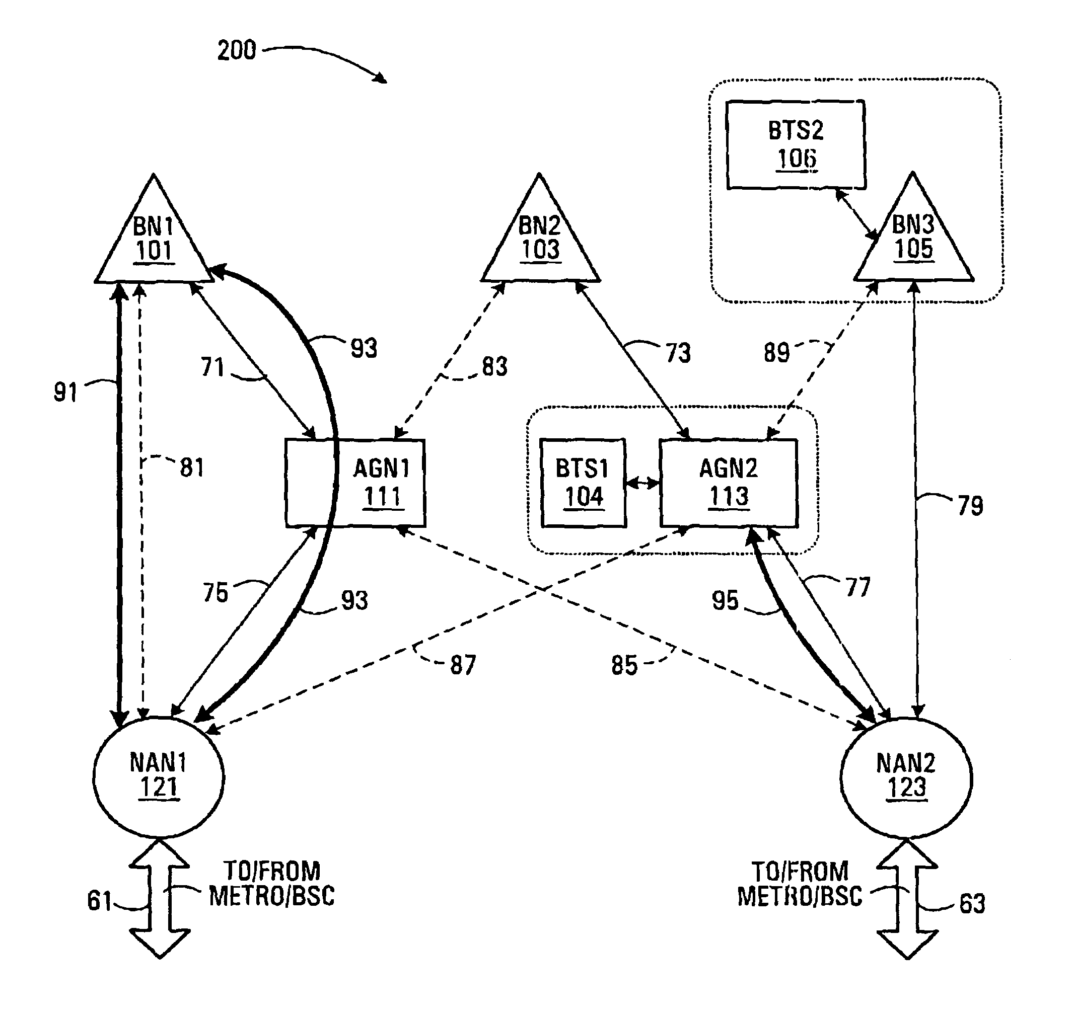
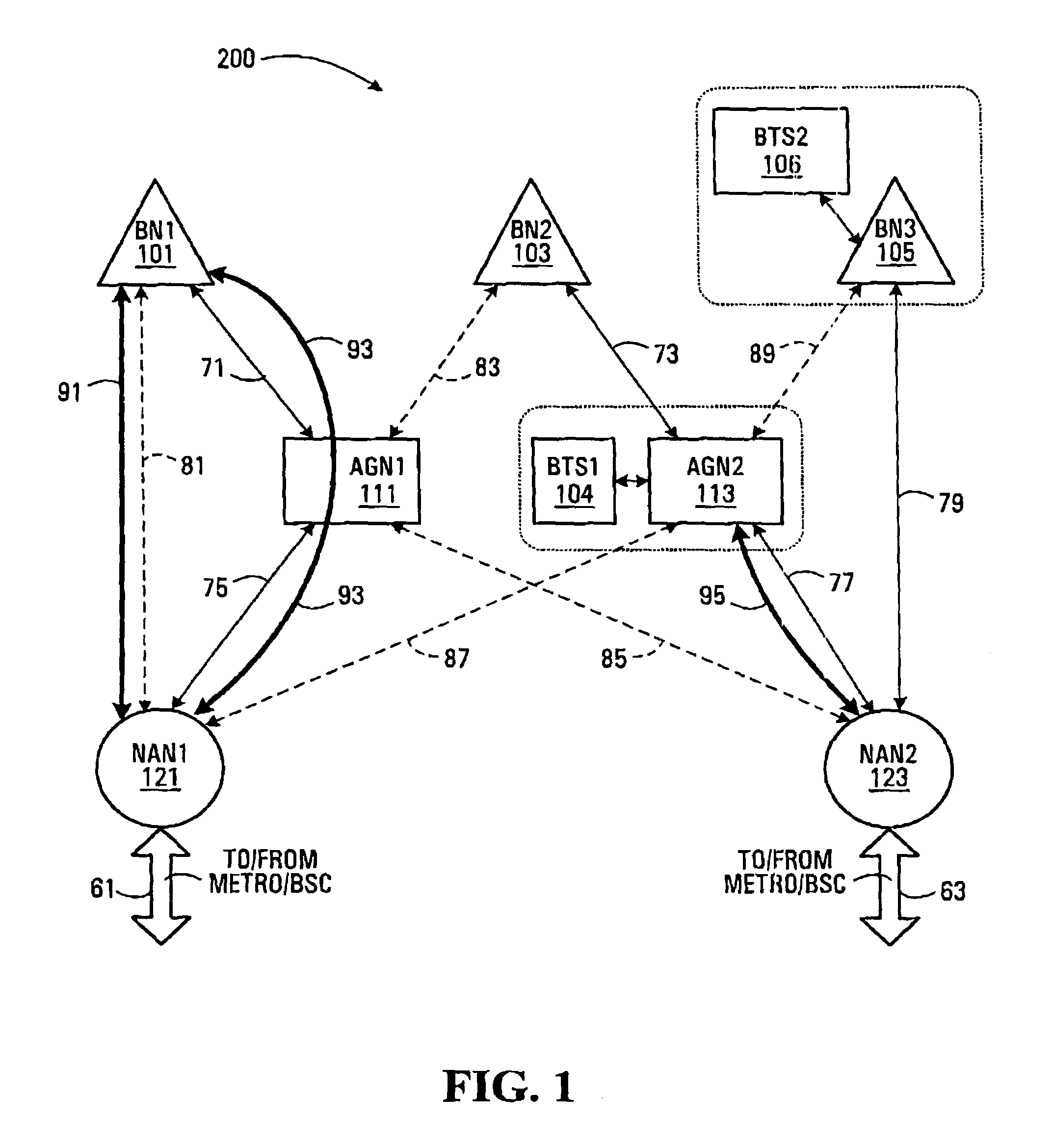
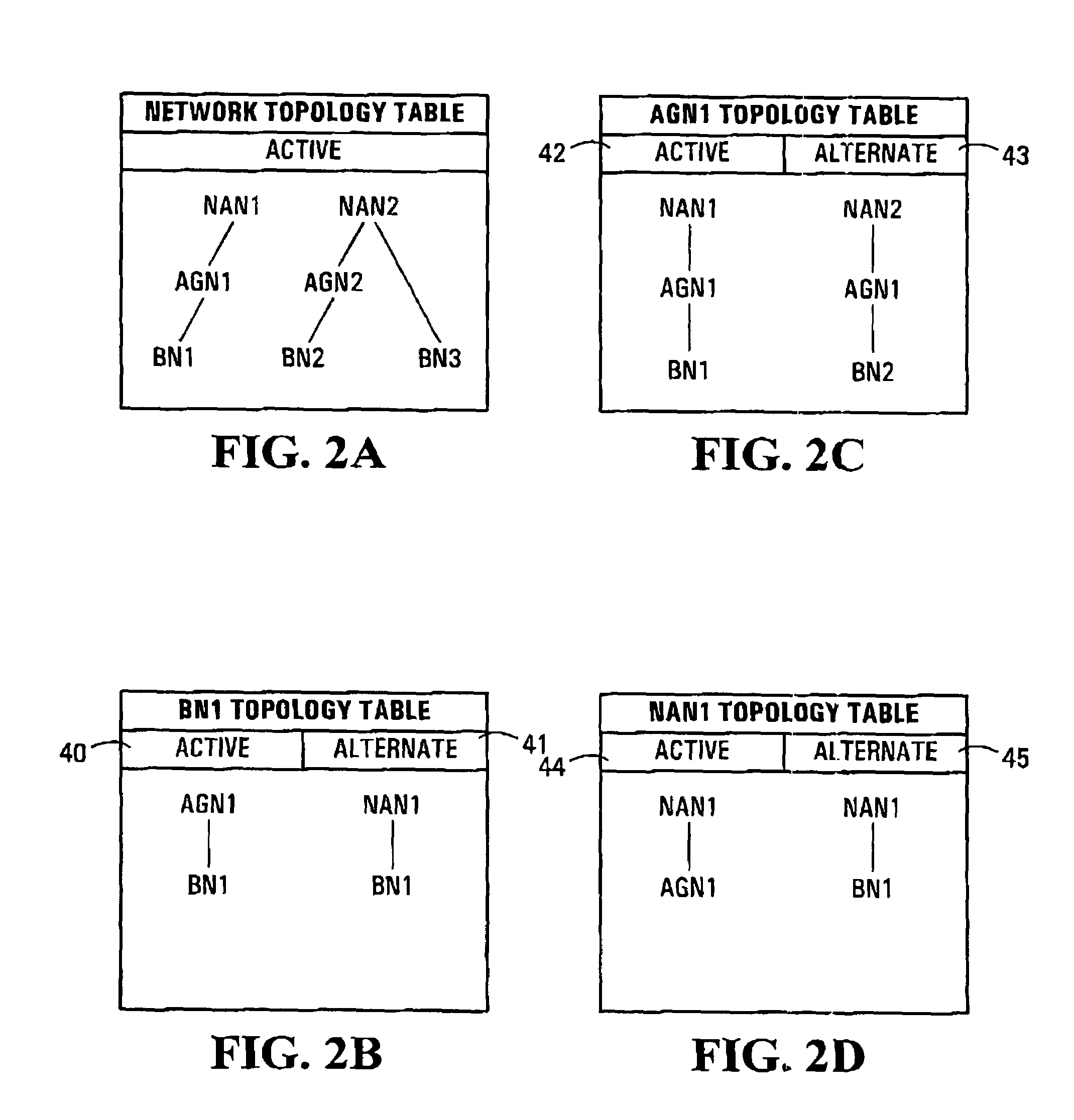
Some embodiments of the invention provide an implementation for a multi-hop wireless backhaul network. These embodiments can advantageously be deployed in dense urban areas and/or co-located with wireless access nodes, such as base-stations of a cellular wireless communication system. Preferably wireless links between constituent network nodes are set-up hierarchically. A basic result of this is that peer-to-peer (child-to-child) communication is generally prohibited and circuits are forced to conform to a topology. The multi-hop wireless backhaul network may be used to carry delay sensitive, high-density last mile circuit traffic over Non-Line-Of-Sight (NLOS) broadband radio links. Moreover, some embodiments of the invention provide a method of path-healing for re-routing of circuit traffic from circuits that have experienced catastrophic failures.

Description

FIELD OF THE INVENTION[0001]This invention relates generally to communication systems and, in particular, to backhaul networks.BACKGROUND[0002]Backhaul networks serve to efficiently transport large amounts of data across and between communication systems. The data carried in a backhaul network typically originates from (or is destined to) multiple sources in one geographic area and is destined for (or originates from) multiple other sources located in other geographic areas. As such, a backhaul network must provide aggregation points for data in each geographic area and efficiently transport aggregations of data between different geographic areas.[0003]Knowledge about the ultimate destinations (e.g. particular end-user devices, web-servers, etc.) of data is not required since backhaul networks do not provide direct access to individual end-users. An aggregation point, provided by backhaul network, is typically co-located with an end-user distribution and access system (e.g. a cellul...

Claims


Application Information

Patent Timeline
Patent Type & Authority Patents(United States)
IPC IPC(8): H04W4/00H04B7/185H04W40/00H04W72/00H04L12/26H04L12/28
CPCH04L41/044H04L41/0896
Inventor PERIYALWAR, SHALINIZHANG, HANGALGIE, GLENNZHU, PEIYINGMATYAS, ROBERTROYER, CLAUDEGAGE, BILLNADEN, JAMESJAVED, ALAUDDIN
Owner MALIKIE INNOVATIONS LTD
Why Eureka
Try Eureka