Multimode optical fiber with low differential mode delay

a multi-mode optical fiber and delay technology, applied in the field of multi-mode optical fibers, can solve the problems of limiting the further increase of bandwidth, sudden and unexpected degradation of fiber bandwidth, and systems based on selective excitation also require more complex field test equipment, so as to achieve the effect of reducing differential mode delay, negative index differences, and convenient and economical fiber manufacturing

Active Publication Date: 2010-01-12
CORNING INC
View PDF14 Cites 52 Cited by
  • Summary
  • Abstract
  • Description
  • Claims
  • Application Information

AI Technical Summary

Benefits of technology

[0012]In the present invention the problem is solved by introduction of special structure in the profile of multimode optical fiber that enables the equalization of the group velocities of higher and lower order modes and is at the same time compatible with current manufacturing processes.
[0013]The present invention uses core extension beneath the cladding level to minimize the differential mode delay among the modes. However, the negative index differen

Problems solved by technology

But even when the bandwidth of 1.5 GHz.km is achieved, differential mode delay proved to be still over 1 ns/km, which limits further increase of bandwidth.
However, the selective excitation of modes in graded index fiber also brings a range of drawbacks.
Optical connectors of insufficient quality, bad splices, certain optical components cabling and process of applying the cables can induce mode coupling between the modes that can result in sudden and unexpected degradation of fiber bandwidth.
The systems that base on selective excitation also require more complex field test equipment.
In addition the selective excitation of modes requires better and narrower range of tolerances for the components that reduces the cost efficiency of the transmission systems.

Method used


Image

  • Multimode optical fiber with low differential mode delay
  • Multimode optical fiber with low differential mode delay
  • Multimode optical fiber with low differential mode delay

Examples


Embodiment Construction

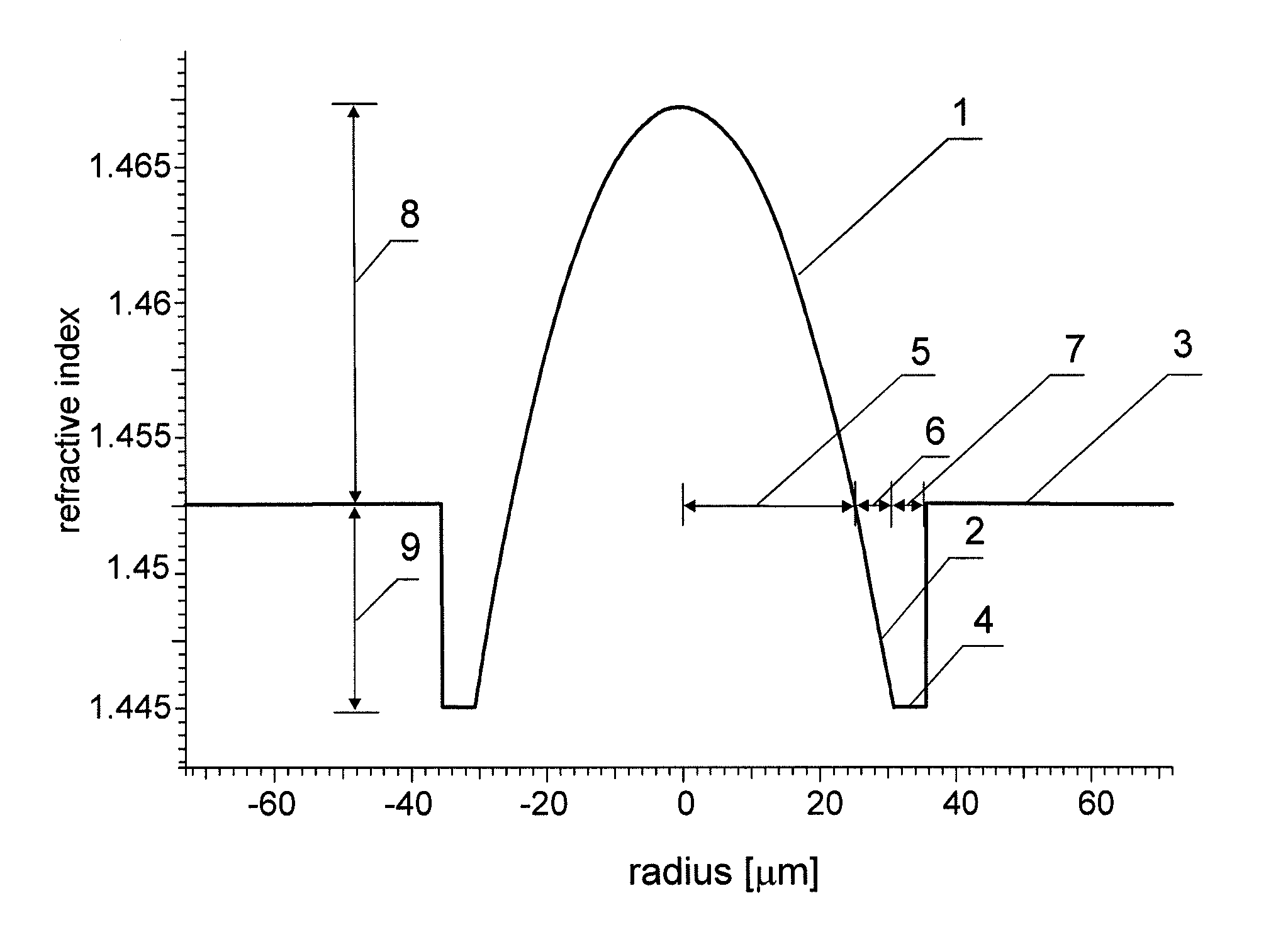
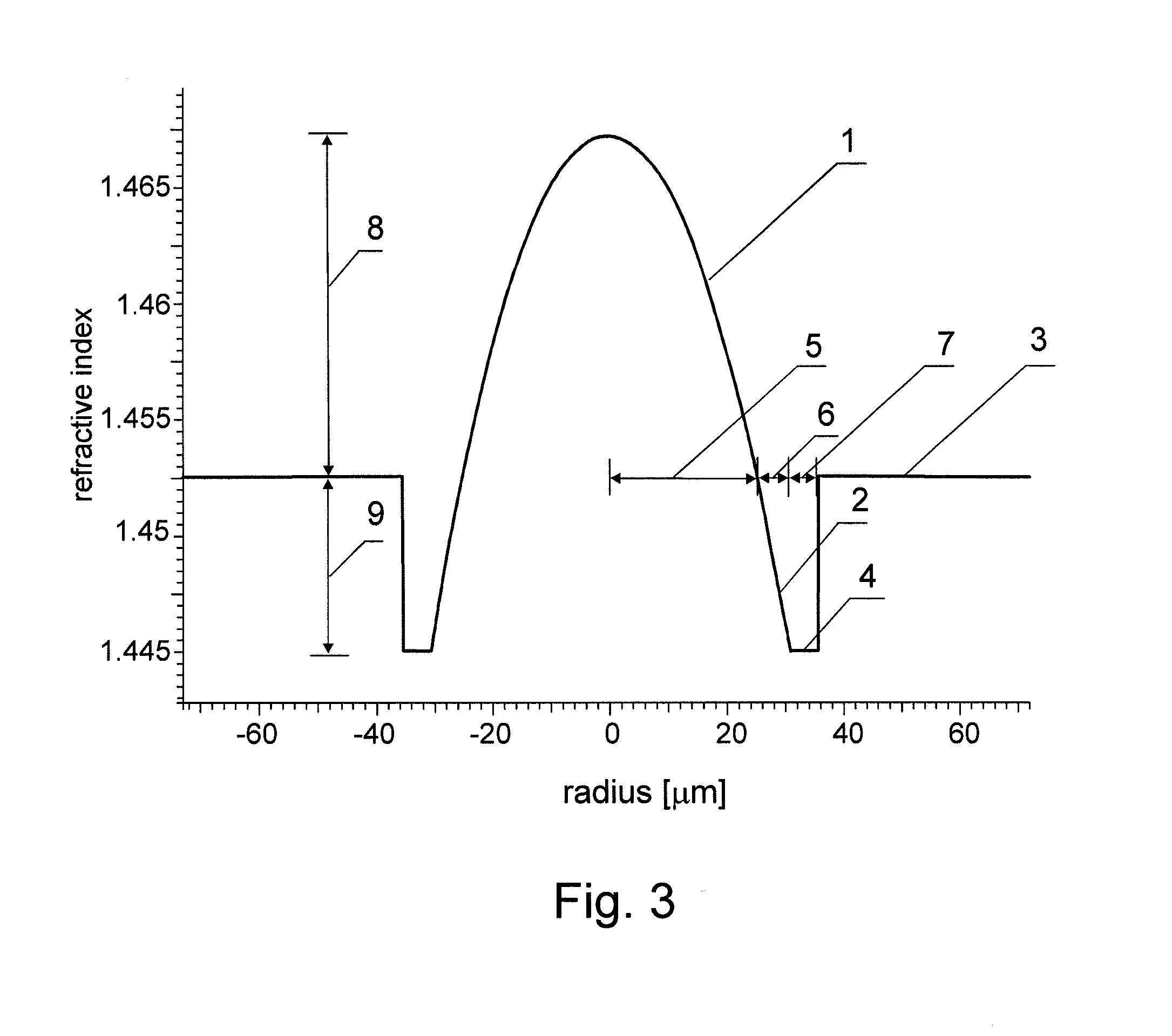
[0024]Detailed numerical analysis has shown that it is not possible to achieve a bandwidth significantly over 1.5 GHz.km when the entire set of modes is excited in a standard multimode fiber. It is generally known that the modal dispersion is minimized by application of the α-profile of the optical fiber that is defined as

n(r)=nmax(1−2Δ(r / a)α)1 / 2 for r

and

nmax(1−2Δ)1 / 2 for r≧a

where r is a coordinate in the radial direction of a cylindrical optical fiber, a is core radius, n(r) is refractive index of the optical fiber at radius r, nmin is the minimum refractive index (in standard fiber this is the refractive index of the cladding), nmax is the maximum refractive index of the fiber core, α is a parameter of the profile, and Δ is defined as

Δ=(nmax2−nmin2) / (2nmax2).

[0025]The profile of standard multimode fibers is composed of a graded index core that is defined by upper equation that describes α-profile of the optical fiber and cladding with the constant refractive index nmin. The α-par...


PUM


Abstract

An optical multimode fiber including a graded index core and an extended gradient core which has a negative refractive index difference with respect to the cladding. The fiber improves the bandwidth, reliability and complexity of the telecommunication systems that are based on multimode fibers. The fiber reduces the differential mode delay among modes. The fiber thereby allows achieving large bandwidth even in the case when the highest order modes are excited. This has positive effects to the conditions that need to be fulfilled by the components such as optical sources, connectors, fiber couplers, other optical components, cables, etc. The fiber eliminates negative impact of the cladding that allows for reduction of fiber core size and the difference between the cladding and the core and thereby allows for achieving the larger bandwidth of optical fiber at lower fiber production cost.

Description

CROSS-REFERENCE TO RELATED APPLICATIONS[0001]This application claims priority to Slovenian patent application 200400216 filed 26 Jul. 2004 and Slovenian patent application 200500190 filed 27 Jun. 2005 and is the national phase under 35 U.S.C. § 371 of PCT / FI2005 / 050284 filed 26 Jul. 2005.FIELD OF THE INVENTION[0002]This invention relates to multimode optical fiber.BACKGROUND OF THE INVENTION[0003]The goal of telecommunication industry is in general the highest possible amount of data transfer in shortest possible time. With the ever increasing number of users and complexity of services there exists a daily increase in demand for the amount of data that can be transferred.[0004]In the art there are variety of solutions that can be applied to achieve high data rate transfer over longer distances. Optical communications, that were topic of intense research and development in past 20 years, make it possible to achieve a bandwidth not comparable to other technologies. The solutions that ...

Claims


Application Information

Patent Timeline
IPC IPC(8): G02B6/028G02B6/036
CPCG02B6/0288G02B6/03627
Inventor DONLAGIC, DENIS
Owner CORNING INC
Why Eureka
Try Eureka