
Oven controlled crystal oscillator

a crystal oscillator and controlled technology, applied in the direction of heat measurement, optical radiation measurement, instruments, etc., can solve the problems of heat generation, temperature difference, and difficult uniform transmission of transistor b>4/b> over the substrate, and achieve reliable, stable temperature control, and improved frequency-temperature characteristics. , the effect of improving the frequency-temperature characteristics

Inactive Publication Date: 2010-01-19
NIHON DEMPA KOGYO CO LTD
View PDF7 Cites 4 Cited by
  • Summary
  • Abstract
  • Description
  • Claims
  • Application Information

AI Technical Summary

Benefits of technology

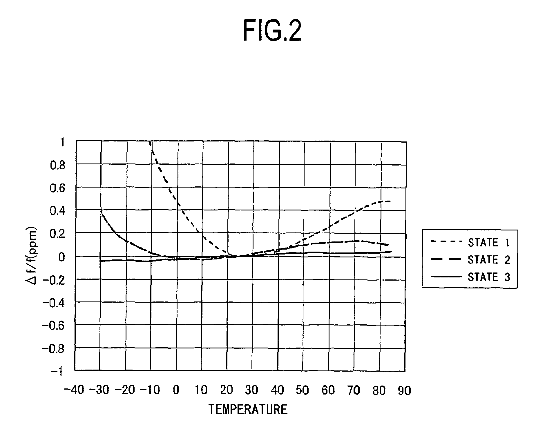
The solution achieves stable and reliable temperature control, significantly improving frequency-temperature characteristics by ensuring uniform heat transmission, maintaining accuracy across varying environmental temperatures without increasing device size or material costs.

Problems solved by technology

However, since the structures of the conventional oven controlled crystal oscillators have a problem that heat generated by the heat generator consisting such as of the resistors 3 and the transistor 4 is hard to be transmitted uniformly over the substrate, a temperature difference can be produced between the temperature sensor 5 and the crystal resonator 2 or any of the other electronic components.
In such a case, reliable temperature control cannot be performed, resulting in degradation of the frequency-temperature characteristics of the output frequency.

Method used


Image

  • Oven controlled crystal oscillator
  • Oven controlled crystal oscillator
  • Oven controlled crystal oscillator

Examples


Embodiment Construction

[0025]Embodiments of the present invention will now be described with reference to the accompanying drawings.

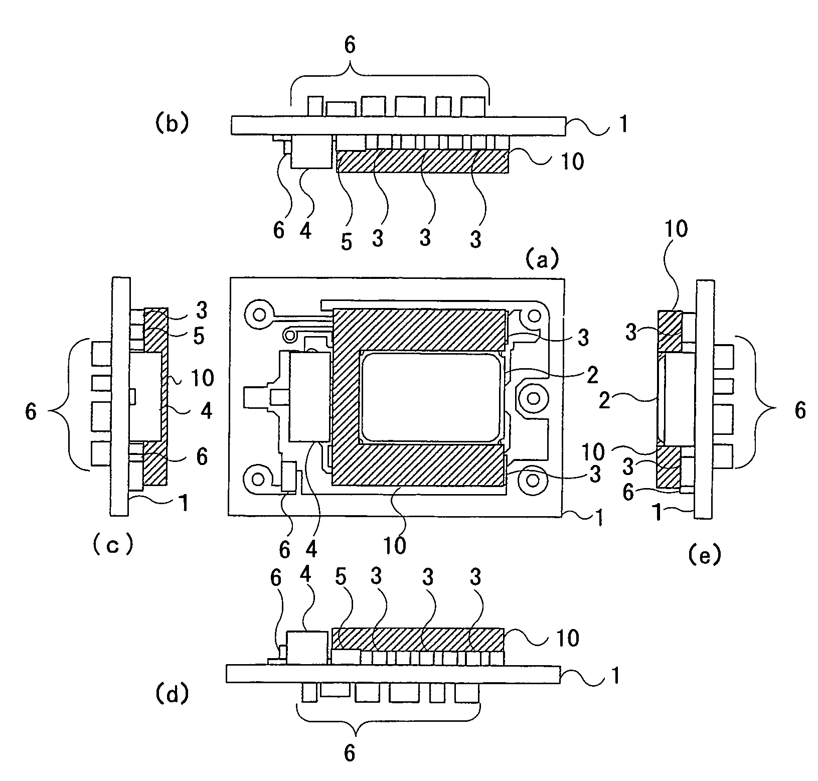
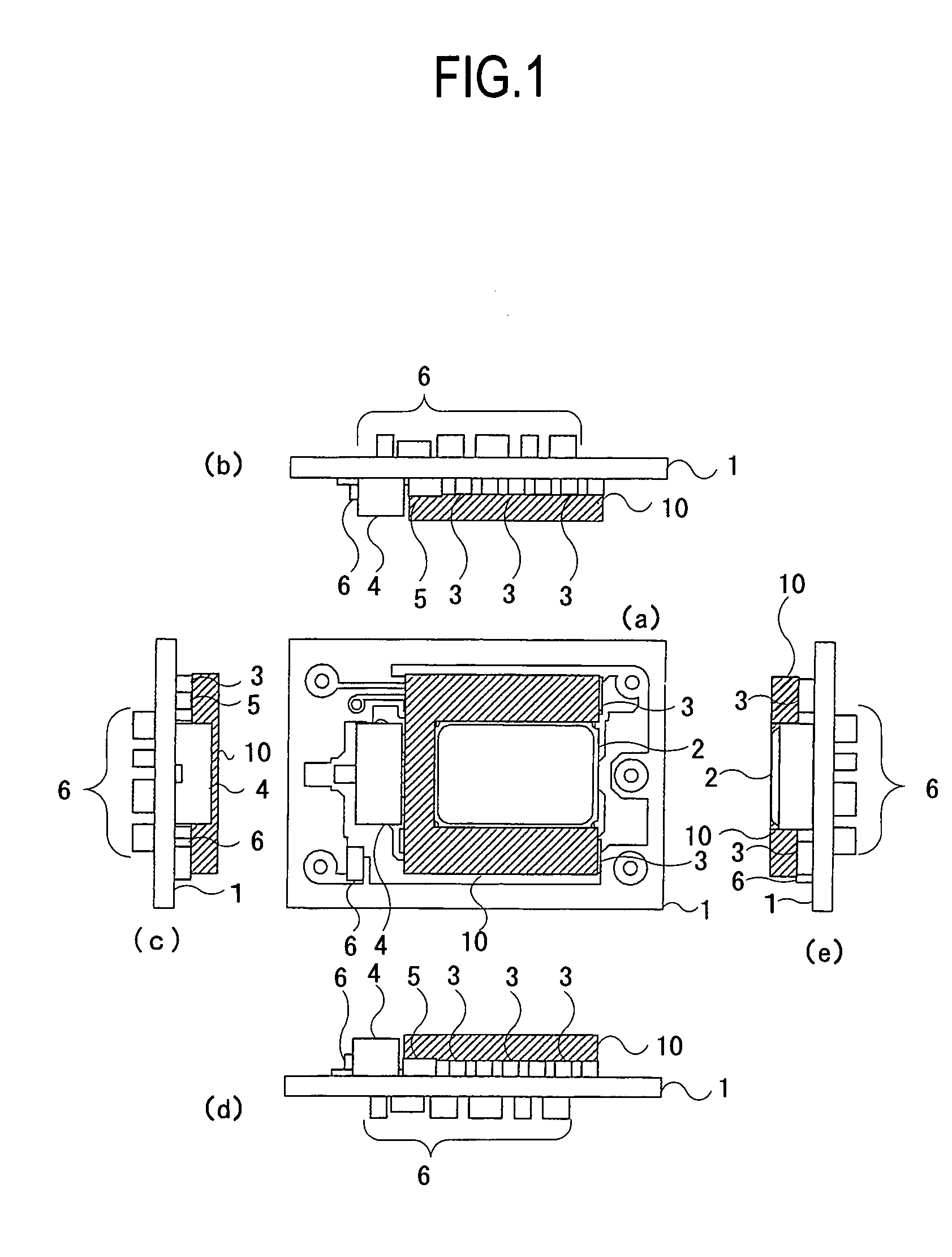
[0026]Oven controlled crystal oscillators according to embodiments of the present invention include a heat-conducting member (high thermal conductivity member) made of a material having high thermal conductivity and located on one side of a substrate, where a crystal resonator is provided, in such a manner to contact a resistor, a transistor, the crystal resonator, and a temperature sensor so as to transmit heat from the resistor and the transistor as a heat generator rapidly to the crystal resonator, the temperature sensor, etc. through the heat-conducting member so as to assure no temperature difference inside the substrate, thereby making it possible to improve the reliability of temperature control and the frequency-temperature characteristics.

[0027]The structure of an oven controlled crystal oscillator according to a preferred embodiment of the present invention will be ...


PUM


Abstract

An oven controlled crystal oscillator capable of uniformly transmitting heat from the heat generator to improve the frequency-temperature characteristics. The oven controlled crystal oscillator includes a high thermal conductivity plate having high thermal conductivity and provided on one side of a substrate, where the crystal resonator is provided, in such a manner to contact the resistors, the transistor, the crystal resonator, and the temperature sensor. This structure can transmit heat from the resistors and the transistor as the heat generator to the crystal resonator and the temperature sensor rapidly with less heat loss to assure a uniform temperature inside the substrate, thereby improving the frequency-temperature characteristics.

Description

BACKGROUND OF THE INVENTION[0001]1. Field of the Invention[0002]The present invention relates to an oven controlled crystal oscillator (OCXO), and particularly to an oven controlled crystal oscillator having stable frequency-temperature characteristics.[0003]2. Description of the Related Art[0004]The oven controlled crystal oscillator is a crystal oscillator having a crystal resonator mounted in a case in which temperature is kept constant. Since the oven controlled crystal oscillator is less likely to be affected by environmental temperature, it has stable frequency characteristics.[0005]The structure of a conventional oven controlled crystal oscillator will be described with reference to FIGS. 4 and 5. FIG. 4 is a sectional view showing the structure of the conventional oven controlled crystal oscillator. FIG. 5 is an explanatory drawing showing the structure of a substrate 1 in the conventional oven controlled crystal oscillator, where (a) is a plan view, (b) is a top view, (c) i...

Claims


Application Information

Patent Timeline
Patent Type & Authority Patents(United States)
IPC IPC(8): H03B1/00
CPCH03L1/04
Inventor KASAHARA, KENJI
Owner NIHON DEMPA KOGYO CO LTD
Learn More