
Method and system for the analysis of saliva using a sensor array

a sensor array and saliva technology, applied in the direction of material analysis, filter regeneration, sequential/parallax process reaction, etc., can solve the problems of physical barrier, difficulty in having relevant markers, and inefficient current methods for their measuremen

Active Publication Date: 2010-01-26
BOARD OF REGENTS
View PDF189 Cites 44 Cited by
  • Summary
  • Abstract
  • Description
  • Claims
  • Application Information

AI Technical Summary

Benefits of technology

The system enables rapid and sensitive detection of cardiac risk factors in saliva, overcoming the limitations of existing methods by providing a cost-effective and efficient means to analyze multiple analytes simultaneously, improving cardiovascular disease screening.

Problems solved by technology

Even though saliva offers advantages in diagnosis by being easily accessible through non-invasive collection, it presents the challenge of having relevant markers of disease at much lower concentrations than blood.
In addition, the viscous nature of the saliva matrix introduces a physical barrier to the development of saliva-specific assays, especially for those utilizing automated fluid delivery systems.
Such problems may only be resolved with a significant dilution of the saliva sample, which consequently requires the diagnostic test to be very sensitive to be effective for saliva samples.
Some of these important factors may indeed be present in saliva but, unfortunately, most of the methods currently used for their measurement are rather inefficient.
These tests require long assays, sophisticated instrumentation, and significant amounts of expensive reagents.
Furthermore, these methods are limited to measuring just one factor at a time and, in most cases, they are not sensitive enough to detect those relevant markers present in saliva at such low concentrations.

Method used


Image

  • Method and system for the analysis of saliva using a sensor array
  • Method and system for the analysis of saliva using a sensor array
  • Method and system for the analysis of saliva using a sensor array

Examples


Embodiment Construction

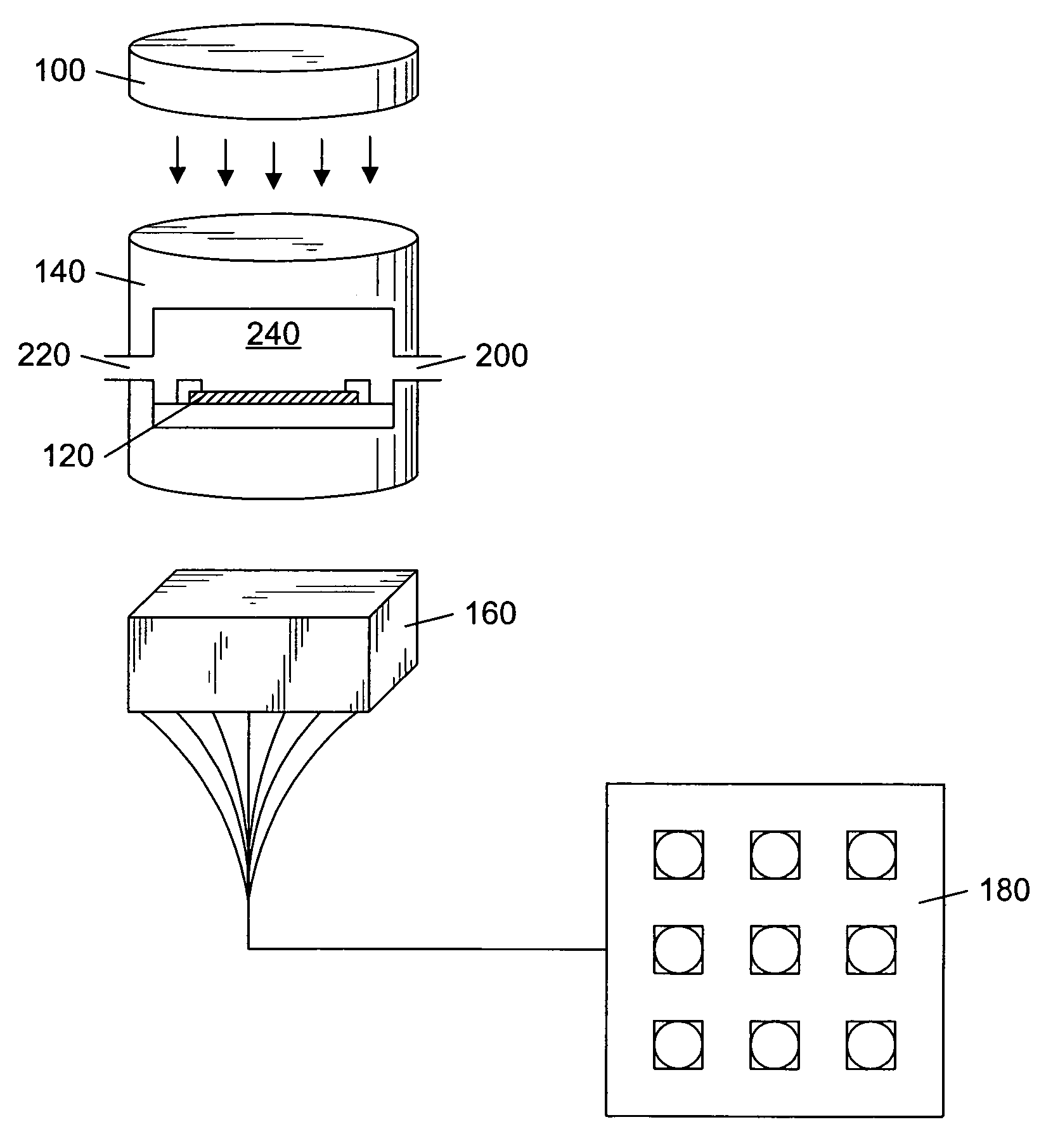
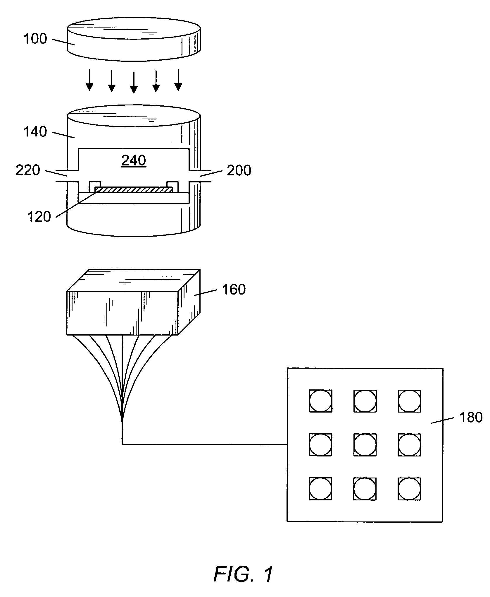
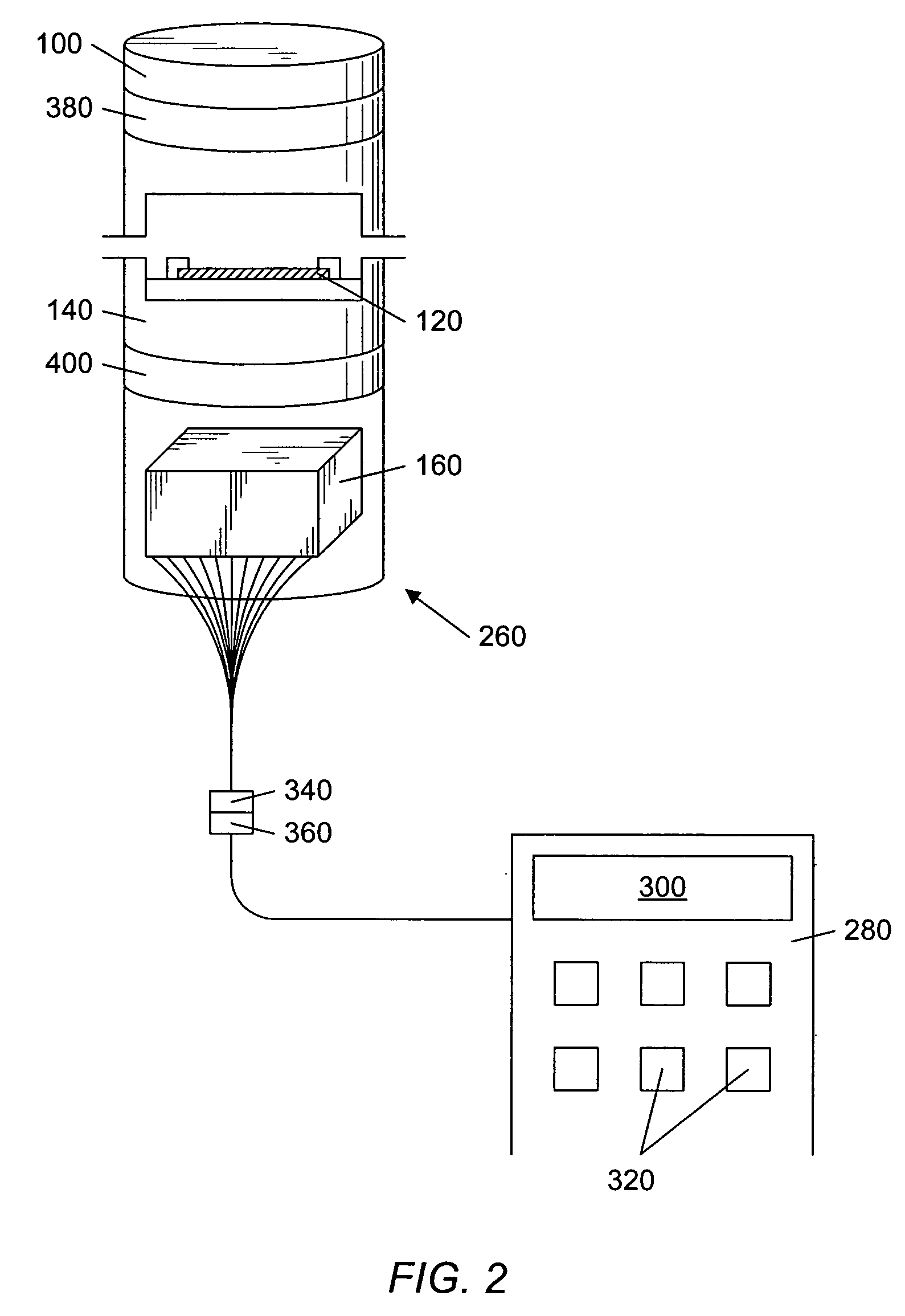
[0065]Herein we describe a system and method for the simultaneous analysis of a fluid containing multiple analytes. The system may generate patterns that are diagnostic for both individual analytes and mixtures of the analytes. The system, in some embodiments, is made of a combination of chemically sensitive particles, formed in an ordered array, capable of simultaneously detecting many different kinds of analytes in saliva rapidly. An aspect of the system is that the array may be formed using a microfabrication process, thus allowing the system to be manufactured in an inexpensive manner.

[0066]Various systems for detecting analytes in a fluid and gases have been described in U.S. Pat. Nos. 6,045,579; 6,680,206; 6,649,403; and 6,713,298; U.S. Patent Application Publication Nos. US 2002-0197622 A1, US 2003-0064422 A1; US 2004-0053322 A1; and US 2003-0186228 A1; and in U.S. patent application Ser. No. 09 / 287,248 all of which are incorporated by reference as if fully set forth herein.

[...


PUM

PropertyMeasurementUnit
pressureaaaaaaaaaa
thicknessaaaaaaaaaa
thicknessaaaaaaaaaa

Abstract

A system for the rapid characterization of analytes in saliva. In one embodiment, a system for detecting analytes includes a light source, a sensor array, and a detector. The sensor array is formed from a supporting member, in which a plurality of cavities may be formed. A series of chemically sensitive particles, in one embodiment, are positioned within the cavities. The particles may produce a signal when a receptor, coupled to the particle, interacts with the cardiovascular risk factor analyte and the particle-analyte complex is visualized using a visualization reagent. Using pattern recognition techniques, the analytes within a multi-analyte fluid may be characterized. In an embodiment, each cavity of the plurality of cavities is designed to capture and contain a specific size particle. Flexible projections may be positioned over each of the cavities to provide retention of the particles in the cavities.

Description

PRIORITY CLAIM[0001]This application claims priority to U.S. provisional patent application No. 60 / 528,946 entitled “Method and System for the Analysis of Saliva Using a Sensor Array” to McDevitt et al. filed on Dec. 11, 2003.BACKGROUND OF THE INVENTION[0002]1. Field of the Invention[0003]The present invention relates to a method and device for the analysis of analytes in saliva. More particularly, the invention relates to the development and use of a sensor array system capable of discriminating multiple analytes in saliva.[0004]2. Brief Description of the Related Art[0005]Interest in saliva as a diagnostic medium has increased exponentially in the last 10 years. In the United States, the need for further research in salivary diagnostics has been emphasized by federal action plans originating from the Office of the Surgeon General (Health and Human Services (HHS), 2000) and the National Institute of Dental and Craniofacial Research, (NIDCR, 1999). It is becoming increasingly import...

Claims


Application Information

Patent Timeline
Patent Type & Authority Patents(United States)
IPC IPC(8): G01N21/00C12M1/34C12M3/00G01N21/64G01N21/76G01N33/00G01N33/44G01N33/543G01N33/545G01N33/566G01N33/92B01J19/00B01L3/00C40B40/10C40B60/14G01N21/77G01N33/53G01N33/544G01N33/552G01N33/68
CPCB01J19/0046B01L3/5025B01L3/502707B01L3/502715B01L3/502738B01L3/502761G01N21/6428G01N21/6454G01N21/77G01N33/5304G01N33/54313G01N33/544G01N33/552G01N33/6887G01N33/92B01J2219/00317B01J2219/005B01J2219/00596B01J2219/00605B01J2219/0061B01J2219/00612B01J2219/00621B01J2219/00626B01J2219/00637B01J2219/00702B01J2219/00725B01L2300/0819B01L2300/0877B01L2400/0487C40B40/10C40B60/14G01N2021/7783G01N2021/7786G01N2201/024G01N2800/32Y10S436/807Y10S436/809
Inventor MCDEVITT, JOHN T.ANSLYN, ERIC V.SHEAR, JASON B.NEIKIRK, DEAN P.CHRISTODOULIDES, NICK J.
Owner BOARD OF REGENTS
Learn More