RF power sensor with chopping amplifier

a technology of rf power sensor and amplifier, which is applied in the direction of power measurement using square-law characteristics, resistance/reactance/impedence, instruments, etc., can solve the problems of power detector, insufficient for many potential applications, and limited sensitivity of commercially available rf power sensors, so as to maximize the dynamic range of the detector and maximize the weak signal sensitivity

Active Publication Date: 2010-01-26
VIASAT INC
View PDF13 Cites 14 Cited by
  • Summary
  • Abstract
  • Description
  • Claims
  • Application Information

AI Technical Summary

Benefits of technology

[0007]In accordance with an exemplary embodiment of the present invention, an amplifier is configured to receive an RF signal. In one exemplary embodiment, the amplifier output is controlled by a pulsed current regulator that “chops” the RF signal by periodically turning the amplifier output “on” and “off” according to a system clock. In this exemplary embodiment, the pulsed amplifier output current feeds the “chopped” RF signal to a Schottky diode. The diode is forward biased to maximize its weak signal sensitivity. To maximize the dynamic range of the detector the diode is operated in the square law region for weak RF signals and in the linear region for other (strong) RF signals. This may involve two converters, a logarithmic converter for the weak signals and a linear converter for the strong signals. The logarithmic converter and linear converter output currents may be summed to form a sum current that is a smoothly monotonically increasing function of the RF signal power. This summed analog output can then be converted to a digital output.

Problems solved by technology

At these frequencies, commercially available RF power sensors have limited sensitivity, pulse settling speed, dynamic range and accuracy.
They also tend to be large in size making them inadequate for many potential applications.
These power detectors, however, have limited operating frequencies or environmental sensitivities that limit their use to applications with operating frequencies of 25 GHz or less or applications that have laboratory like environmental conditions.
RF power sensors operating in these regions have limited sensitivity, pulse settling speed, dynamic range and accuracy for a variety of reasons.
Inductive noise currents and component variations often add unwanted noise and errors.
Other low frequency and DC noise sources sometimes introduce significant errors in power measurement.

Method used


Image

  • RF power sensor with chopping amplifier
  • RF power sensor with chopping amplifier
  • RF power sensor with chopping amplifier

Examples


Embodiment Construction

[0013]While exemplary embodiments are described herein in sufficient detail to enable those skilled in the art to practice the invention, it should be understood that other embodiments may be realized and that logical electrical and mechanical changes may be made without departing from the spirit and scope of the invention. Thus, the following detailed description is presented for purposes of illustration only.

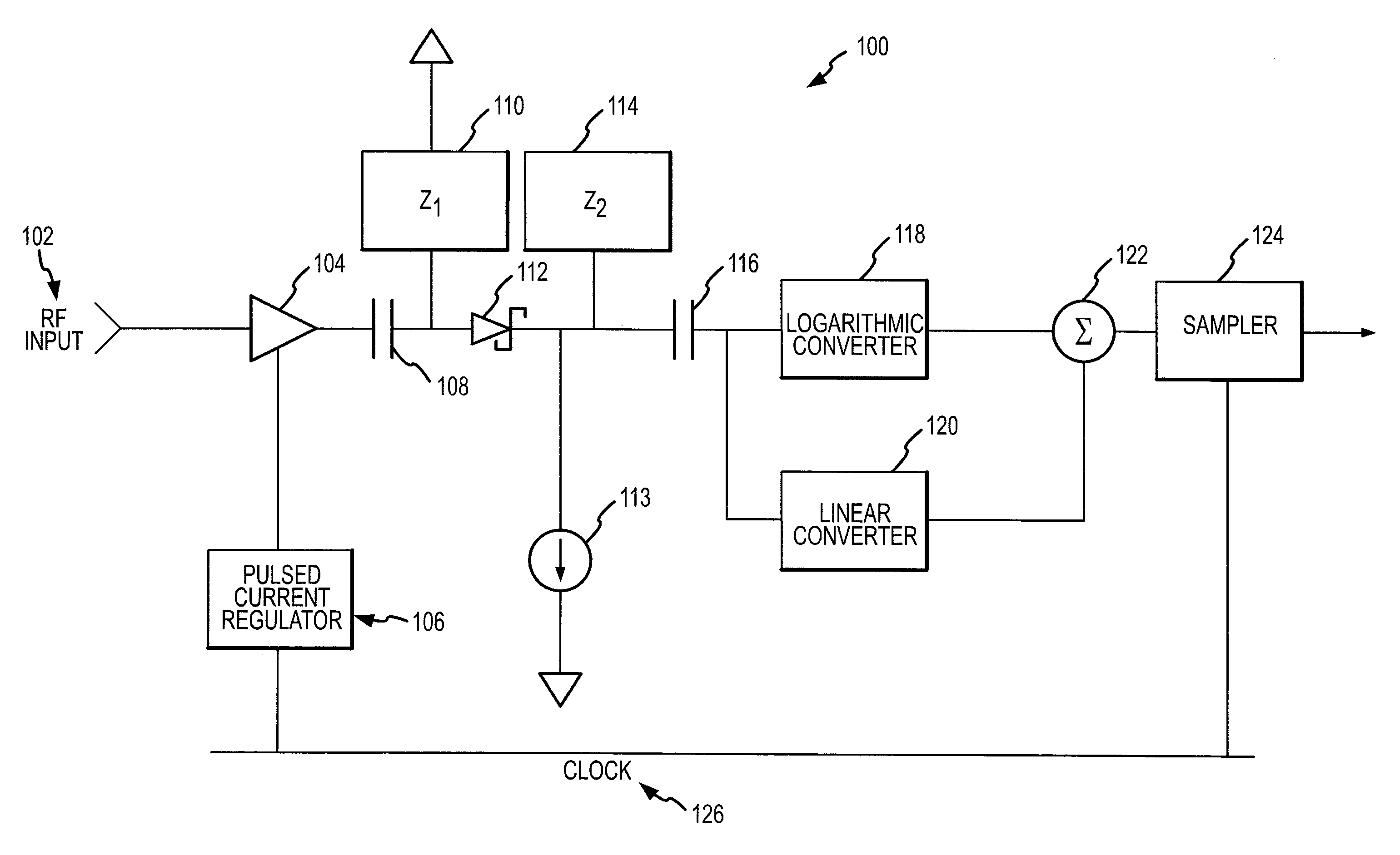
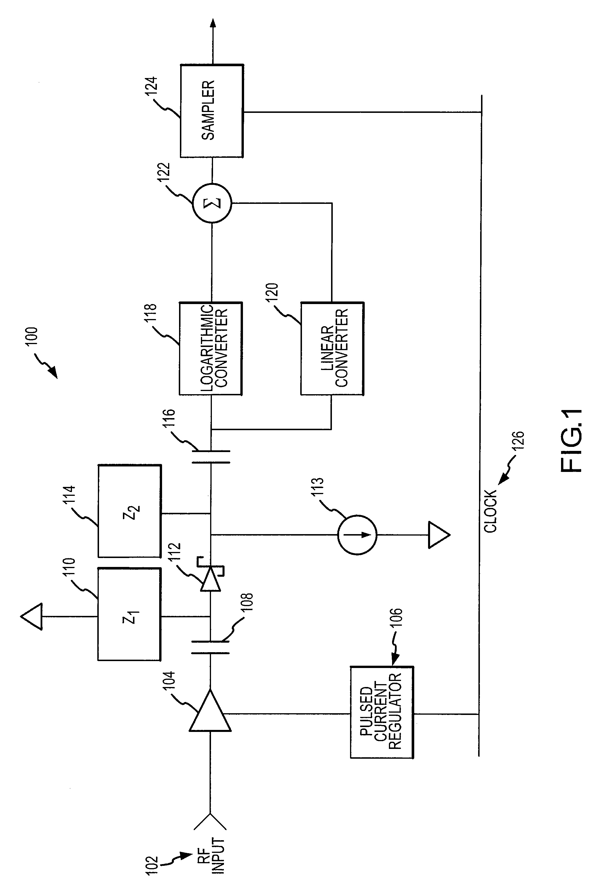
[0014]In accordance with an exemplary embodiment of the present invention, and with reference to FIG. 1, an RF sensor 100 comprises an RF input 102, an amplifier 104, a Schottky diode 112, a logarithmic converter 118, a linear converter 120, a summing junction 122, a sampler 124 and / or a pulsed current regulator 106. RF sensor may further comprise a blocking capacitor 108, a high pass capacitor 116, and / or a current source 113.

[0015]In accordance with one exemplary embodiment of the present invention, RF input 102 is connected to the input of amplifier 104. Amplifier 104 is co...


PUM


Abstract

An RF power detector having a wide dynamic range may comprise a chopping amplifier and is configured to detect pulsed high frequency RF signals. The chopping amplifier controlled by a bias current regulator amplifies and chops an RF signal by periodically enabling and disabling the amplifier according to a system clock. The chopped high frequency RF signal feeds a Schottky diode biased to operate in the square law region for weak signals. The Schottky diode voltage is tapped and high pass filtered. The voltage drives a logarithmic and linear converter. The converter outputs are summed to produce an output voltage that is a repeatable and stable monotonically increasing function of the RF power.

Description

CROSS-REFERENCE TO RELATED APPLICATIONS[0001]This application is a non-provisional application of and claims priority to U.S. Provisional Application No. 60 / 798,233 filed on May 5, 2006 and entitled “High Accuracy RF Power Detector”, which application is incorporated herein by reference.FIELD OF INVENTION[0002]The present invention relates to radio frequency (RF) power detectors. More particularly, the invention relates to a sensitive and accurate RF power detector having a wide dynamic range and configured to sense short pulses of very high frequency RF signals.BACKGROUND OF THE INVENTION[0003]Many communications and RADAR systems operate at RF frequencies of Ku Band or higher. In many of these systems it is necessary to continuously monitor and adjust the transmitted RF power level and the gain of the receiver (or transmitter) in order to compensate for changing link conditions such as atmospheric changes in weather conditions, interference, movement or changes in orientation of t...

Claims


Application Information

Patent Timeline
Patent Type & Authority Patents(United States)
IPC IPC(8): G01R25/02
CPCG01R21/10H03G1/00
Inventor LANG, DAVIDLOPEZ, NOEL
Owner VIASAT INC
Why Eureka
Try Eureka