
Screw conveyor of rotary hearth furnace for discharging reduced iron

a technology of rotary hearth furnace and conveyer, which is applied in the direction of furnaces, charge manipulation, lighting and heating apparatus, etc., can solve the problems of screw blade constant frictional force, screw blade wear for a short period, and cannot be continuously used, so as to reduce the friction amount of the screw blade, improve the water-cooled effect, and reduce the frictional force

Inactive Publication Date: 2010-02-02
NIPPON STEEL & SUMIKIN ENG CO LTD +1
View PDF12 Cites 2 Cited by
  • Summary
  • Abstract
  • Description
  • Claims
  • Application Information

AI Technical Summary

Benefits of technology

[0012]The present invention is to provide a reduced iron discharging screw conveyer of a rotary hearth furnace, which can reduce maintenance frequency of the screw conveyer and improve an operation rate of the rotary hearth furnace in a simple structure by extending a life span of a screw blade of the reduced iron discharging screw conveyer provided in the rotary hearth furnace.
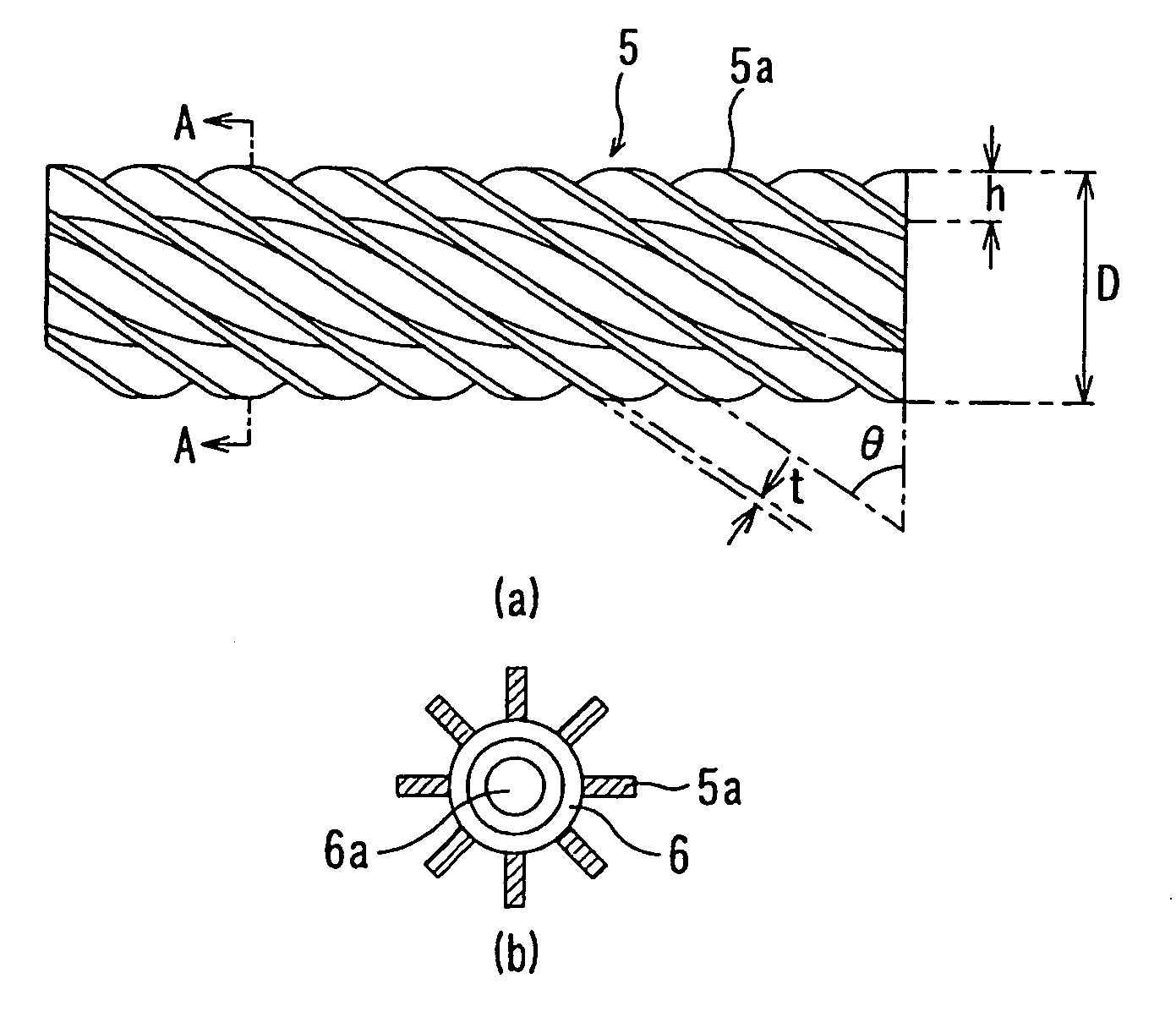
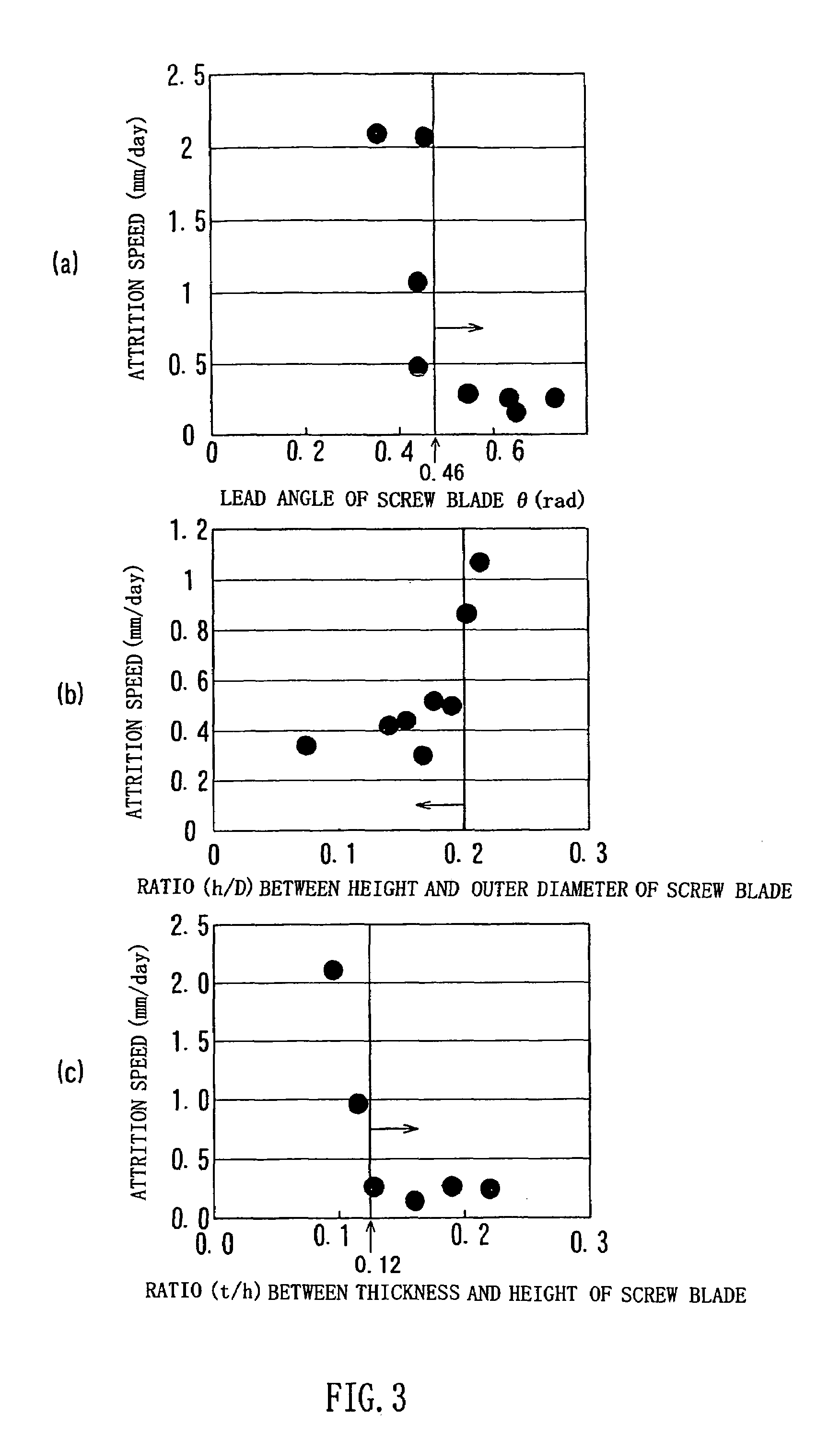
[0015]According to the reduced iron discharging screw conveyer of the present invention, by setting the lead angle of the screw blade so as to satisfy the above condition of expression (1), it is possible to reduce the friction force between the screw blade and the rotary hearth. In addition, when a water-cooled structure is provide in the rotary shaft, by setting the ratio (h / D) between the height of the screw blade and the outer diameter of the screw conveyer so as to be smaller than 0.2 and setting the ratio between the thickness and the height of the screw blade so as to be larger than or equal to 0.12, it is possible to improve the water-cooled effect applied to the screw blade from the rotary shaft and reduce the friction amount of the screw blade. In addition, by forming the screw blade on the rotary shaft via weld, the screw conveyer satisfying the above condition is easily manufactured. When the life span of the screw blade can be extended, it is possible to improve the operation rate of the rotary hearth furnace and reduce the equipment expenses per production volume.

Problems solved by technology

In addition, the screw blade constantly receives frictional force since the screw blade contacts a surface of the rotary hearth when scraping out the reduced iron lying on the rotary hearth.
Therefore, in the conventional structure, the screw blade is worn for a short period due to the attrition and can not be continuously used for a long period.
When the force for pushing up the screw conveyer is wrongly adjusted, the apparent weight of the screw conveyer may be excessively reduced.
In addition, if the force of the elevating cylinder for pushing up the screw conveyer is reduced using a spring and soon, the number of components is increased and the apparatus increases in cost.

Method used


Image

  • Screw conveyor of rotary hearth furnace for discharging reduced iron
  • Screw conveyor of rotary hearth furnace for discharging reduced iron
  • Screw conveyor of rotary hearth furnace for discharging reduced iron

Examples


Embodiment Construction

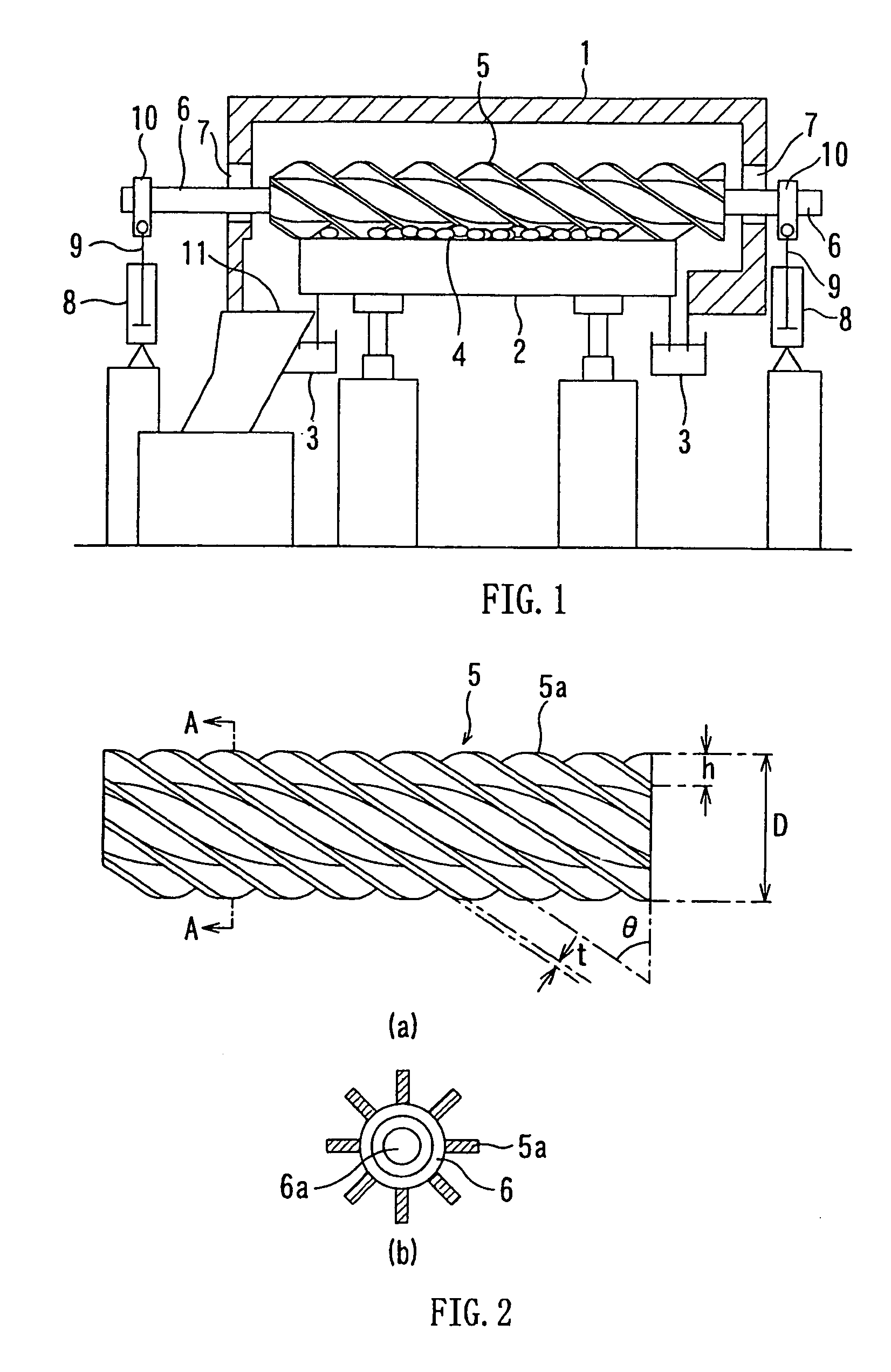
[0021]FIG. 1 is a schematic diagram showing an example of a rotary hearth furnace in which a reduced iron discharging screw conveyer according to the present invention (hereinafter referred to as “screw conveyer”) is arranged.

[0022]A rotary hearth 2 is arranged on a lower side of a furnace casing 1 of the rotary hearth furnace and can rotate in a horizontal plane about its longitudinal axis. A water sealing process is performed between the furnace casing 1 and the rotary hearth 2 using a circular water sealing channel 3 for maintaining an atmosphere in the rotary hearth furnace.

[0023]A screw conveyer 5 is used for discharging a reduced iron pellet 4 obtained through a reduction processing of a pellet to an outside area. Both ends of a rotary shaft 6 pass through long holes 7 of the furnace casing 1 and are supported by a piston rod 9 of a cylinder 8 provided out of the furnace via a bearing 10 in a manner that the rotary shaft 6 can move up and down. The bearing 10 is fixed to the p...


PUM

PropertyMeasurementUnit
lead angleaaaaaaaaaa

Abstract

A reduced iron discharging screw conveyer is provided in a rotary hearth furnace and discharges reduced iron out of the rotary hearth furnace. The rotary hearth furnace produces the reduced iron by charging and heating a pellet including metallic oxide and coal material onto a rotary hearth rotating in a horizontal plane. The reduced iron discharging screw conveyer has a rotary shaft and a screw blade which is spirally formed on an outer surface of the rotary shaft. A lead angle θ of the screw blade 5a satisfies a condition of “0.46 rad ≦θ≦0.79 rad”. A ratio (h / D) between height h of the screw blade and an outer diameter D of the screw conveyer is smaller than 0.2, and a ratio (t / h) between thickness t and height h of the screw blade is larger than or equal to 0.12.

Description

TECHNICAL FIELD[0001]The present invention relates to a reduced iron discharging screw conveyer for discharging a reduced iron out of a furnace, which is provided in a rotary hearth furnace.BACKGROUND ART[0002]A rotary hearth furnace is used for producing reduced iron. In the rotary hearth furnace, a pellet is prepared using coal material and metallic oxide such as iron ore and iron making dust. The reduced iron is produced by charging and heating (reducing) the pellet onto the rotary hearth which rotates in a horizontal plane in the rotary hearth furnace (refer to patent documents 1, 2, 3).[0003]FIG. 5 is a schematic diagram showing an example of a rotary hearth furnace. In FIG. 5, reduced iron is produced by charging a pellet on a rotary hearth 21 through a pellet charge opening 22 and heating (reducing) the pellet. The rotary hearth 21 rotates in the horizontal plane in a rotary hearth furnace 20. The reduced iron is moved toward the circumference of the rotary hearth 21 by a scr...

Claims


Application Information

Patent Timeline
Patent Type & Authority Patents(United States)
IPC IPC(8): C21B13/10
CPCC21B13/0046C21B13/105F27B9/16F27B9/30F27B9/39F27D3/08
Inventor SHIMA, SHINJINAKAYAMA, TOSHITAKANAGATOMI, MASAHIDE
Owner NIPPON STEEL & SUMIKIN ENG CO LTD
Learn More