Solfire solar concentrator and pointer structure

a solar concentrator and pointer technology, applied in the direction of machines/engines, transportation and packaging, light and heating equipment, etc., can solve the problems of increasing the cost, increasing the difficulty of thermal management of waste heat, and increasing the cost. , to achieve the effect of reducing costs, reducing costs, and eliminating some of the costs associated

Inactive Publication Date: 2010-02-09
MCDERMOTT PATRICK P
View PDF31 Cites 31 Cited by
  • Summary
  • Abstract
  • Description
  • Claims
  • Application Information

AI Technical Summary

Benefits of technology

[0008]The method and apparatus of the invention, called SOLFIRE, takes advantage of a new two-phase Subambient Cooling System (SACS) designed and patented by Raytheon (McKinney, Tex.), which can efficiently remove tens, even hundreds kilowatts of waste heat without the need for expensive refrigeration units, requiring only a moderate-sized liquid pump, a reservoir for the working fluid, and a vapor-to-air heat exchanger. In order to reduce costs, ZENTEK is proposing a large aperture structure consisting of a continuous path piping system that can act as the heat exchanger for the SACS system, thus eliminating some of the costs associated with SACS, eliminating a separate heat exchanger and the fan-motor required to move air thought the heat exchanger.

Problems solved by technology

In each case, however, the size of the PV receiver is relatively small, with a short focal length lens.
But, if the size of the system (larger lenses, receivers, and focal lengths) is increased to achieve “economies of scale,” the thermal management of waste heat (that not converted to electrical energy by the PV conversion) becomes technically challenging.
These often entail large investment of equipment, require additional kilowatt of electrical energy to operate refrigeration equipment, all of which adds considerably to the cost, and weighs against “scaling up” the high concentration (hundreds of suns) PV systems.

Method used


Image

  • Solfire solar concentrator and pointer structure
  • Solfire solar concentrator and pointer structure
  • Solfire solar concentrator and pointer structure

Examples


Embodiment Construction

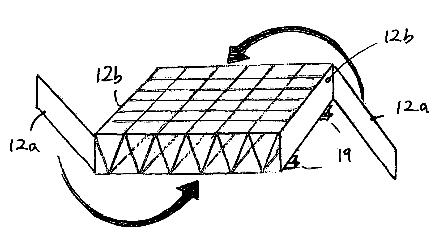
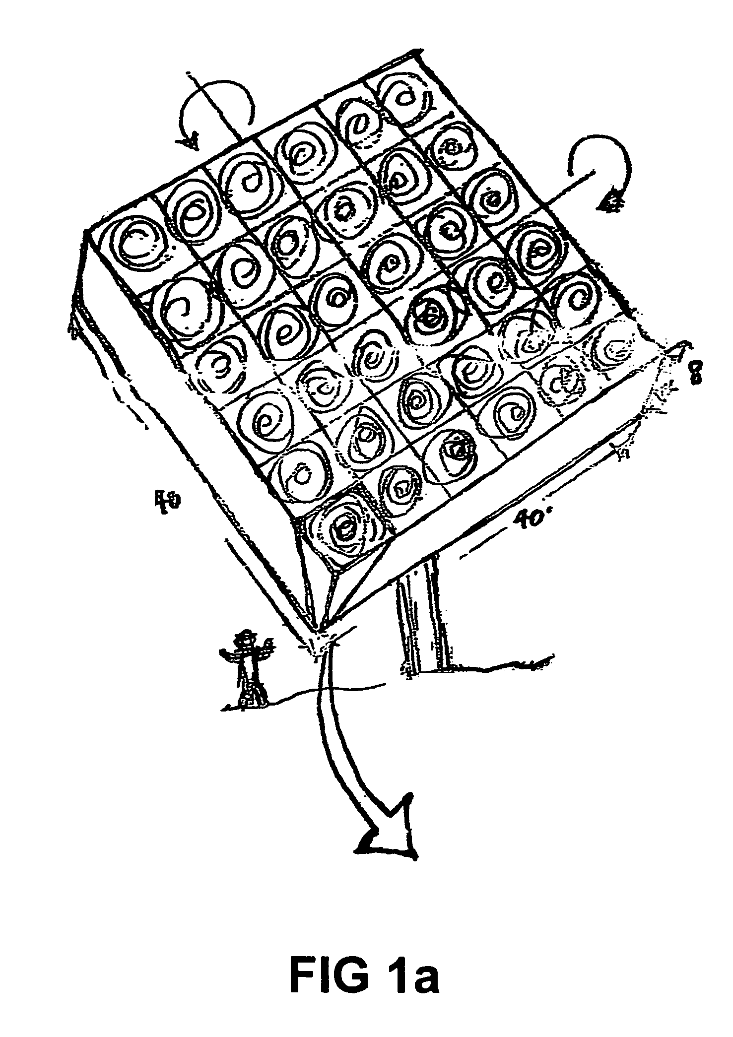
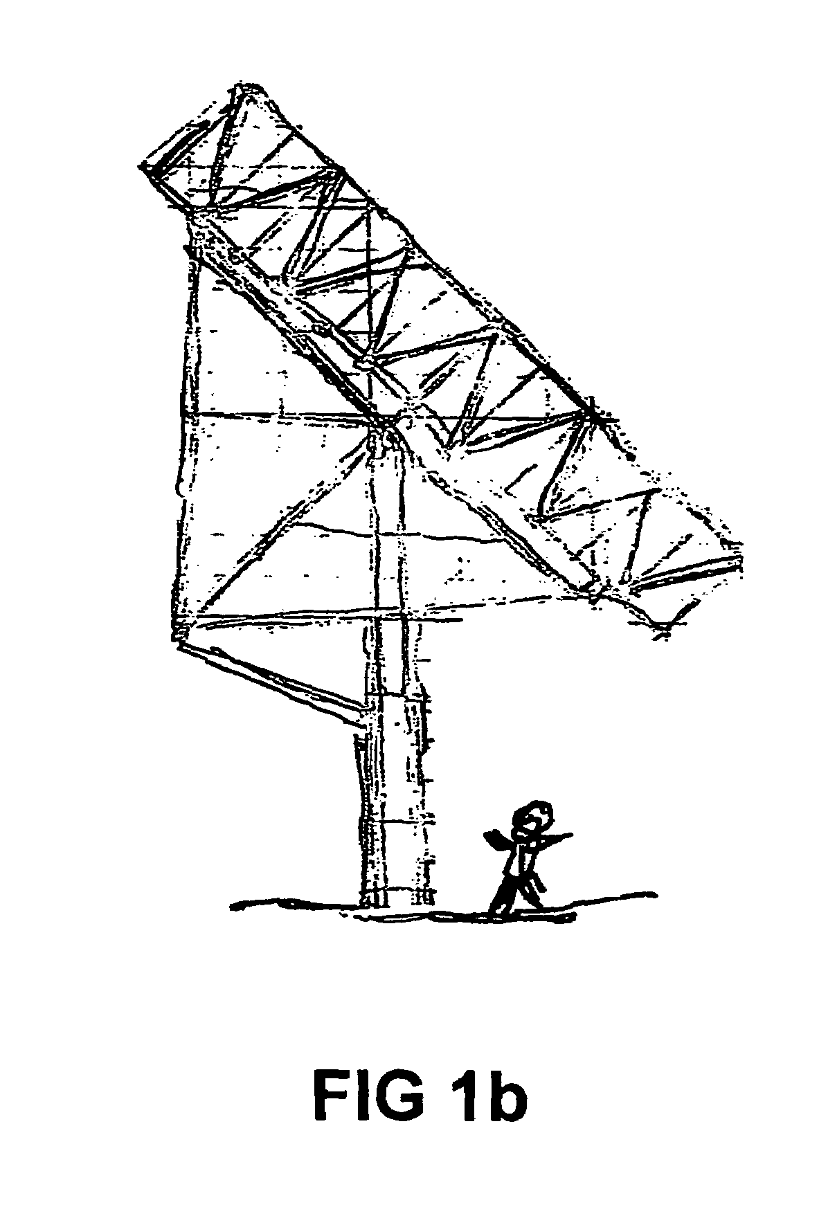
[0044]The SOLFIRE 36 kW array illustrated in the following descriptions has 36 lenses and 36 PV cell receivers in a 40 ft×40 ft square array structure 11 8 ft deep as shown in FIGS. 1a (perspective view) and 1b (side view). FIG. 1c is a blow up of on of the 36 cells that make up the array. The lenses and receivers are held in place by a tetrahedral substructure, hereafter referred to as the Modular Cell, MC. FIG. 1c shows the MC as a inverted tetrahedral structure with the base formed by four 2 meter (6.6 ft) long pipes 1 (1″ galvanized pipe), connected at each corner 2 with four 2.66 meter (8.25 ft) long pipes 3 forming the sides of the inverted tetrahedron, joined together at the apex 4, providing a very stabile platform for the PV receiver 5. The receiver is located at the focal point of the flat Fresnel lens 6 contained in the base of the tetrahedron. The dotted lines 7 indicate sites where the MC is connected into the larger array structure.

[0045]FIG. 1d shows an open frame ver...


PUM


Abstract

Solar generators have Fresnel lenses and spaced heat absorbers or photovoltaic cells for receiving focused solar rays. Heat is removed from their backs by boiling liquid in conical receivers. Pins or fins extend rearward into the receivers from the heat absorbers or photovoltaic cells. Liquid supply to the receivers is controlled by valves and floats or sensors. Tubes remove steam or vapor from the receivers for driving generators or for cooling photovoltaic cells. Hinged tubes which form the foldable support conduct the steam to generators and condense the vapor. Liquid is returned to a holding tank, is pumped to a distribution tank and is conducted by some of the structural tubes back to the valved receivers.

Description

[0001]This application claims the benefit of U.S. Provisional Application No. 60 / 749,050 filed Dec. 12, 2005, which is hereby incorporated by reference in its entirety.BACKGROUND OF THE INVENTION[0002]In several previous terrestrial systems, very high levels of solar concentration (hundreds of suns) have been achieved with reflective optics to generate steam for powering turbines and direct conversion of heat to electricity via Sterling engines or photovoltaic (PV) cell for direct electrical conversion. Refractive optics in many forms, mainly Fresnel lenses, has been used for moderate levels of concentration (e.g., 20 suns) using flat or curved lenses to focus on a linear PV receiver. Flat or domed Fresnel lenses can achieve hundreds of suns of concentration using spot PV receivers.[0003]MIDWAY Corporation, Chicago, Ill., for example, marketed a flat aperture configuration, with multiple Fresnel lenses concentrating light on small PV cells (1-2 cm2) distributed on the back plane of ...

Claims


Application Information

Patent Timeline
Patent Type & Authority Patents(United States)
IPC IPC(8): B60K16/00F24J2/36
CPCF24J2/085F24J2/20F24J2/36H01L31/0547H01L31/0543Y02E10/44Y02E10/52Y02E10/43F24S10/50F24S20/50F24S23/31
Inventor MCDERMOTT, PATRICK P.
Owner MCDERMOTT PATRICK P
Why Eureka
Try Eureka