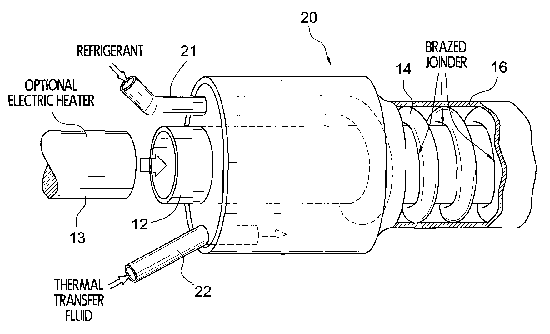
[0014]In accordance with one aspect of the invention a versatile heat exchanger employs an encircling flow of one fluid medium to cool or heat a general fluid
thermal transfer medium that flows generally longitudinally. This can be termed a “three-way heat exchanger” because it can also include an internal electrical heater for the thermal transfer fluid. In one example, the exchanger incorporates a length of metallic tubing for a first fluid medium, the tubing being wrapped helically between a inner mandrel element or
solid mandrel and an outer tubular
enclosure. The second fluid medium flows in a generally parallel or counterflow path helically between the turns of the helically wrapped tubing, being contained between the previously mentioned mandrel and hollow
enclosure.
Thermal energy transfer takes place directly through the walls of the tubing. The
interior space within the mandrel, if said mandrel is a hollow tube, can accommodate an optional electronic heater for independent or cumulative heating of fluid media. The advantages of this mounting include the facility for changing heaters, either for repair or replacement without incurring the need for breaking into the flow circuits of either the refrigerant or
heat transfer fluid. Such construction also allows for the use of an electrical heater without the necessity for having extra plumbing to accommodate said heater. The construction also places the heater in very close intimate
thermal contact with the
heat transfer fluid without the need for constructing any further heat exchangers. The heat-transfer fluid flows at a relatively
high velocity confined within its
helical path and thus exhibits a
high heat transfer coefficient. In this regard the construction of the three-way heat exchangers provides an extremely economical and compact
system for exchanging heat amongst
heat transfer fluid, vapor-cycle
refrigeration circuit and electrical heater. In addition to these virtues, the refrigerant, being contained within a metallic tube of circular cross-section can exist at high
temperature and pressure without incurring any danger of rupturing the containing vessel.
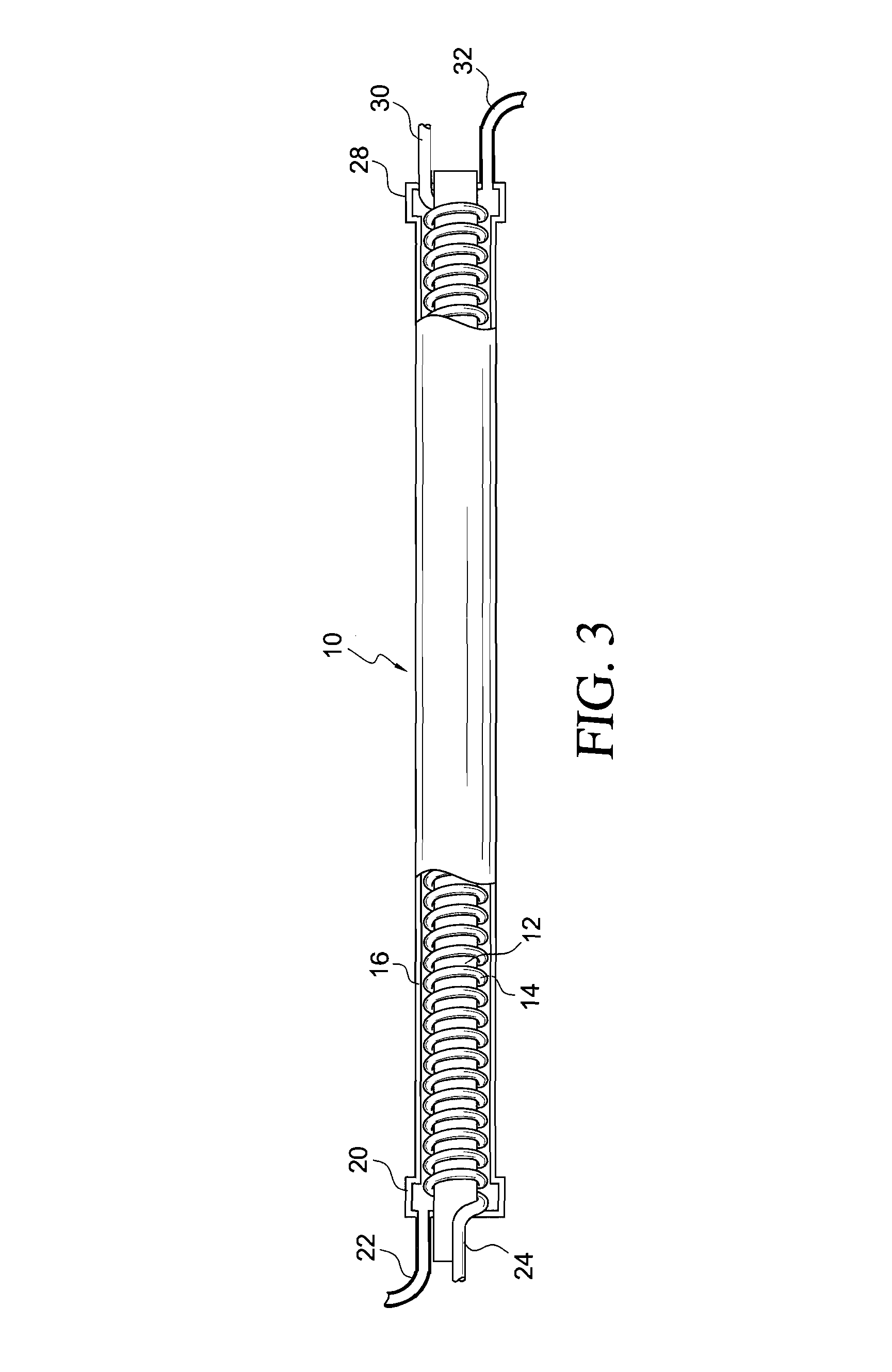
[0015]The first fluid flowing within the
helical tubing can be a refrigerant at a given temperature, and the second fluid can then be a thermal transfer fluid. If the turns of the
helical tubing are brazed, soldered or welded to the boundary walls, and said tubes are fabricated of thermally conductive material heat transfer is very efficient. Furthermore, the unit is very rugged and can withstand wide temperature differentials and high pressures of both the fluids contained within the exchanger.
[0017]The first thermal media may be a pressurized liquid, gaseous or
mixed phase refrigerant flowing within the helically wrapped tubing while thermal transfer fluid flows helically about the exterior of the mandrel, confined by the turns of the helical tubing. Such flows may be either in counterflow or parallel to each other, depending on the characteristics of the two flows and of the system that employs the exchanger. The size and spacing of the helical tubing determines the volumetric ratio of the two flows, and with a typical
refrigeration cycle the unit can be small but highly efficient.
[0018]This construction, using concentric elements, also facilitates incorporation of input and output ports and headers. The
enclosure tubing about the helical wrapping need only lead to radial expansions to allow input and output of the second fluid, while the helical tubing can be longitudinally coupled at its ends for input and output of the first fluid media. This arrangement is particularly thermally efficient because of the complete intermixing of the thermal transfer fluid and the short heat transfer paths through the intervening tubing walls.
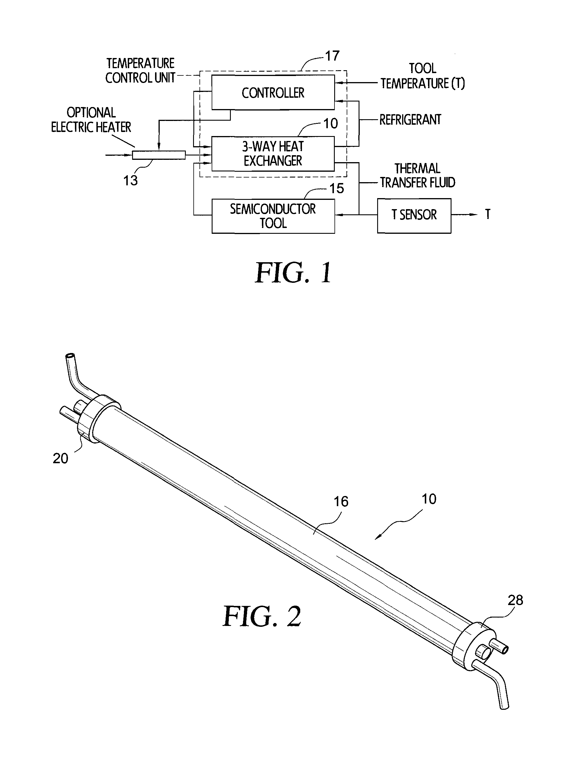
[0020]A TCU that makes advantageous use of this compact, versatile heat exchanger includes a single system operating on a liquid / vapor
refrigeration cycle and providing a pressurized ambient temperature refrigerant. Two or more channels, each including a separate process tool, may be separately controlled by this one
energy source.
Refrigerant is selectively expanded in each channel under commands from the controller to provide any cooing needed to each channel. The expanded refrigerant in each channel is directed to one pathway in the respective heat exchanger. A
second pathway through the heat exchanger is in a loop for thermal transfer fluid pumped from a reservoir and ultimately through the process tool for
temperature control, and then back to the reservoir. Heaters internally disposed within the heat exchangers can be used to increase the temperature capabilities for the process tool.
System costs may be reduced, if higher
heat capacity is desired, by using two or more compact heat exchangers in parallel. Furthermore, a single controller may be used to control the temperature of separate process tools, each having its own control loop for thermal transfer fluid. This permits a single refrigeration cycle system to be used with a single control to operate two or more process tools with different thermal demands at different target temperatures.
[0022]Another low cost but efficient
temperature control unit in accordance with the invention uses this heat exchanger between a thermal transfer loop and an active refrigeration loop to alternatively heat or chill a process tool. In a conventional flow path, pressurized refrigerant after condensation is fed as a
mixed phase gas through an expansion valve to establish a selected chilled level at the tool. Both of the alternate heating and cooling paths are isolated from each other by unidirectional check valves in the lines feeding to the heat exchanger. The return path to the compressor extends via a desuperheater valve and a compressor accumulator, to the compressor input. For greater efficiency, a subcooler may also be used. This enables the system to operate in different
modes, to heat or cool a process tool, or to use a combination heating mode with a time modulated
control mode using both hot and cold sources. It also can be used for rapid heating changes and rapid cooling transitions, as desired, when changes are needed.

