Antenna autotrack control system for precision spot beam pointing control

a control system and spot beam technology, applied in the direction of antenna details, antennas, electrical devices, etc., can solve the problems of excessive gimbal stepping, excessive gimbal stepping, and use feedback control strategies, so as to prevent excessive gimbal stepping, improve performance, and improve the effect of 0.01 degrees in total antenna pointing

Active Publication Date: 2010-02-16
LOCKHEED MARTIN CORP
View PDF20 Cites 23 Cited by
  • Summary
  • Abstract
  • Description
  • Claims
  • Application Information

AI Technical Summary

Benefits of technology

[0007]The system according to the invention provides improved performance by taking advantage of the fact that the antenna pointing error is periodic at the spacecraft orbit period of 24 hours. Therefore, it is possible to estimate the periodic antenna pointing error using an adaptive or fixed gain estimator and step the antenna gimbal to cancel it before a significant error in antenna pointing actually accrues. The estimator is designed to capture the significant harmonic components of the error signal and to reject the measurement noise, thereby preventing excessive gimbal s

Problems solved by technology

The drawback of prior-art autotrack systems is that they use feedback control strategies that react only to the presently sensed pointing error.
Typically, the threshold is set to a value of one gimbal step, so the tracking error will be at least this much and generally more due to latencies in the system im

Method used


Image

  • Antenna autotrack control system for precision spot beam pointing control
  • Antenna autotrack control system for precision spot beam pointing control
  • Antenna autotrack control system for precision spot beam pointing control

Examples


Embodiment Construction

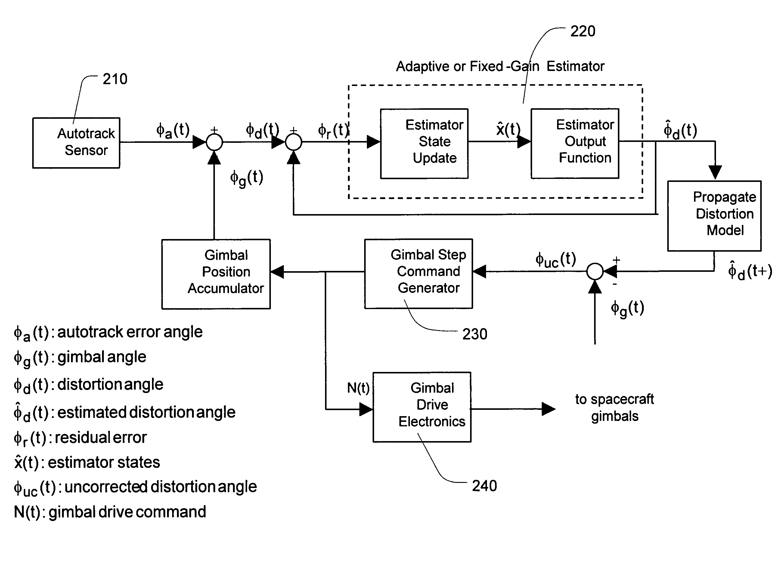
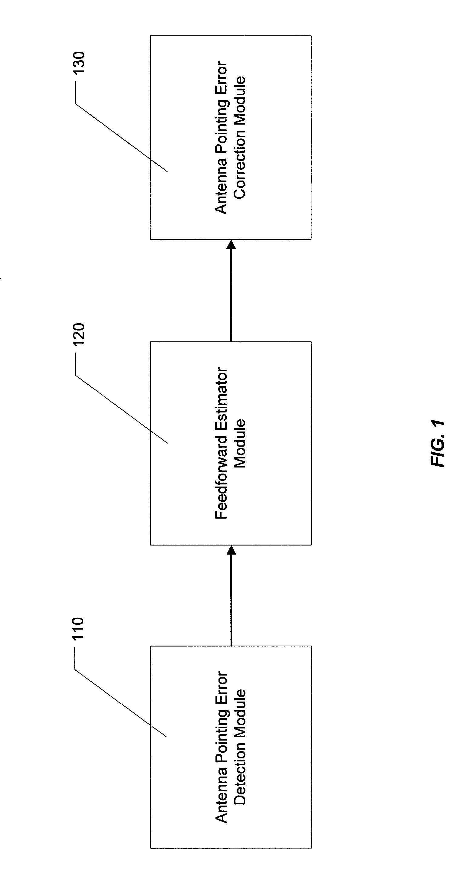
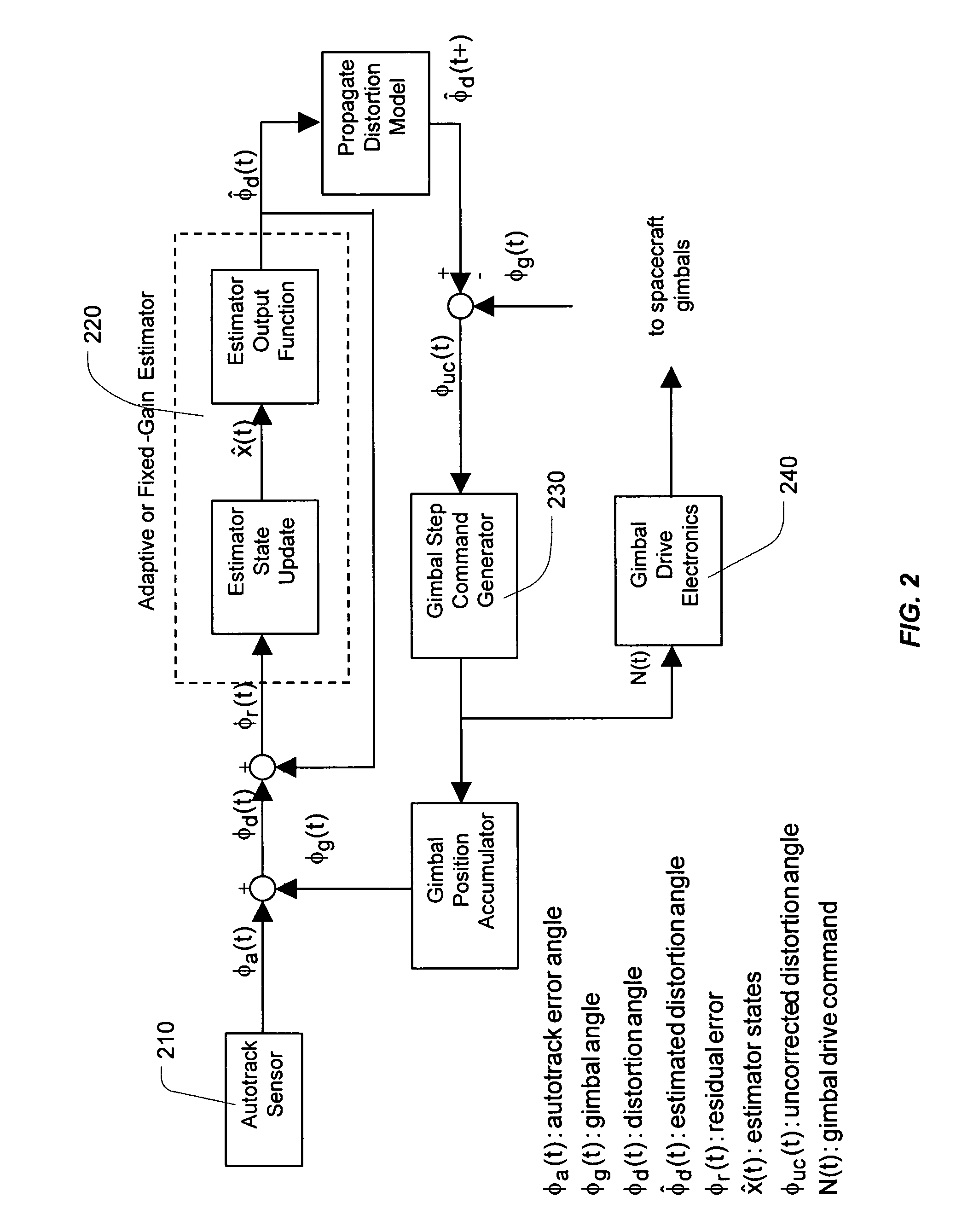
[0020]FIG. 1 illustrates a block diagram for a system for improving spacecraft antenna pointing accuracy according to the present invention. As shown in FIG. 1, the system according to the present invention comprises antenna pointing detection module (110) for detecting and measuring spacecraft antenna pointing error, feedforward estimator module (120) for learning spacecraft antenna pointing error behavior from the measured spacecraft antenna pointing error and generating a predictive output of estimated future spacecraft antenna pointing error, and antenna pointing error correction module (130) for prospectively correcting spacecraft antenna pointing error based on the predictive output from the feedforward estimator module.

[0021]In contrast to the prior-art feedback control approaches, the present invention takes advantage of the periodic nature of spacecraft antenna pointing error behavior which has the period of 24 hours. As well known to those skilled in the art, the spacecraf...


PUM


Abstract

The present invention provides a system and a method for improving spacecraft antenna pointing accuracy utilizing feedforward estimation. The present invention takes advantage of the fact that spacecraft antenna pointing error has periodic behavior with a period of 24 hours. Thus, unlike the prior art feedback systems which blindly correct antenna pointing error continuously reacting only to presently sensed error, the present invention takes an intelligent approach and learns the periodic behavior of spacecraft antenna pointing error. Then, an estimate of antenna pointing error at a particular time going forward is predicted based on the learned model of the periodic behavior of the antenna pointing error. The predicted estimate is then used to correct or cancel out the antenna pointing error at a particular time in the future. The result is more accurate correction of spacecraft antenna pointing error by more than a factor of two.

Description

STATEMENT AS TO RIGHTS TO INVENTIONS MADE UNDER FEDERALLY SPONSORED RESEARCH OR DEVELOPMENT[0001]Not Applicable.BACKGROUND OF THE INVENTION[0002]1. Field of the Invention[0003]The present invention relates generally to spacecraft antenna pointing error correction, and specifically to a system and a method for improving spacecraft antenna pointing accuracy utilizing feedforward estimation.[0004]2. Description of the Related Art[0005]A significant trend in satellite communications is the use of spot beams to provide targeted services to specific urban regions and population centers. Examples of A2100 spacecraft that include spot beam payloads are Echostar 7, Rainbow-1, and the Echostar X spacecraft. Given the typical small coverage region diameter of 200 to 400 km, accurate pointing is critical to minimize the necessary beam diameter and payload power. To achieve high accuracy beam pointing, prior art systems use autotrack antenna feeds and receivers that sense the antenna pointing er...

Claims


Application Information

Patent Timeline
IPC IPC(8): H01Q3/00
CPCH01Q1/288H01Q3/08
Inventor GOODZEIT, NEIL E.WEIGL, HARALD J.
Owner LOCKHEED MARTIN CORP
Why Eureka
Try Eureka