Current measurement using inductor coil with compact configuration and low TCR alloys

a technology of inductor coils and compact configurations, applied in the direction of transformers/inductance details, inductances with magnetic cores, etc., can solve the problems of insufficient compact form factor of coils manufactured with current technology, complicated manufacturing processes, and inability to meet the requirements of modern electronic devices, etc., to achieve the effect of high degree of current measurement accuracy

Active Publication Date: 2010-02-23
CYNTEC
View PDF22 Cites 8 Cited by
  • Summary
  • Abstract
  • Description
  • Claims
  • Application Information

AI Technical Summary

Benefits of technology

[0013]Another object of the present invention is to provide a new structural configuration and manufacture method for manufacturing an inductor with simplified manufacturing processes to produce inductors with improved form factors having smaller height and size and more device reliability. This invention discloses an inductor that includes conducting wire-winding configurations that are more compatible with automated manufacturing processes for effectively reducing the production costs. Furthermore, with enhanced automated manufacturing processes, the reliability of the inductors is significantly improved.

Problems solved by technology

For those of ordinary skill in the art, an inductive coil is usually not suitable for current measurement due to the variation of resistance with temperature.
Additionally, the configurations and the process of manufacturing a high current inductor coil are still faced with technical challenges that inductor coils manufactured with current technology still does not provide sufficient compact form factor often required by application in modern electronic devices.
Furthermore, conventional inductor coils are is still manufactured with complicate manufacturing processes that involve multiple steps of epoxy bonding and wire welding processes.
The production cost is also increased due to the requirements that the lead frame and the coil must be separately manufactured.
The manufacture processes are further complicated as several welding and bonding steps are required to securely attach the welding ends of the flat wire to the welding points of the lead frame.
The production yields and time required to manufacture the inductor coil are adversely affected due to the more complicate inductor configurations and multiple boding and welding manufacturing processes.
These inductors however have a difficulty that the inductor reliability is often a problem.
Additionally, the manufacturing methods are more complicate and the production costs are high.
The high production costs are caused by the reasons that the configurations are not convenient by using automated processes thus the inductors as disclosed do not enable a person of ordinary skill to perform effective cost down in producing large amount of inductors as now required in the wireless communications.
In addition to above discussed limitations, conventional inductive coils typically composed of copper that has low resistance.
A measurement of current may therefore incur a 0.43% error when there is one degree of change in temperature.
This requirement of using a separate resistor leads to more complicate manufacturing processes, higher production costs and lower production yields.

Method used


Image

  • Current measurement using inductor coil with compact configuration and low TCR alloys
  • Current measurement using inductor coil with compact configuration and low TCR alloys
  • Current measurement using inductor coil with compact configuration and low TCR alloys

Examples


Embodiment Construction

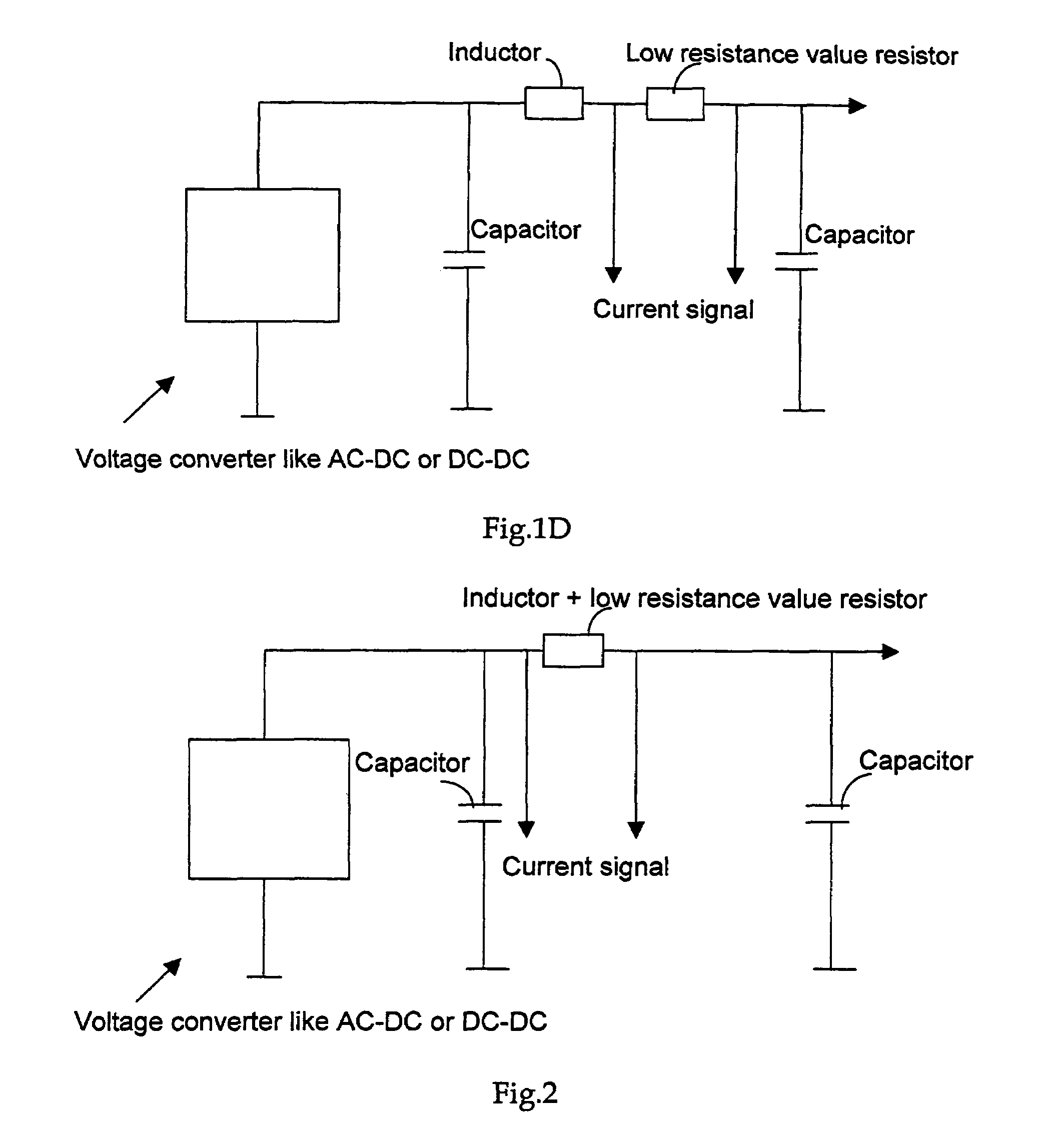
[0025]Referring to FIG. 2 for an improved circuit diagram with a new inductive coil 100 composed of alloys of low temperature coefficients of resistance. A separate resistor as that shown in FIG. 1D is no longer required. A current measurement can be directly performed over the inductive coil 100. An alloy of low TCR may be selected from a group of alloys that may include Cu—Mn—Ni, Cu—Ni, Ni—Cr, and Fe—Cr alloys. The table below shows some examples of alloys with achievable low TCR for each of these alloys.

[0026]

specificresistance valueTCRMaterial systemmicro ohm-mppm / degCu—Mn—Ni system0.44±10Cu—Ni system0.49±200.31800.154200.16500.43700Ni—Cr system1.082001.12260Fe—Cr system1.4280

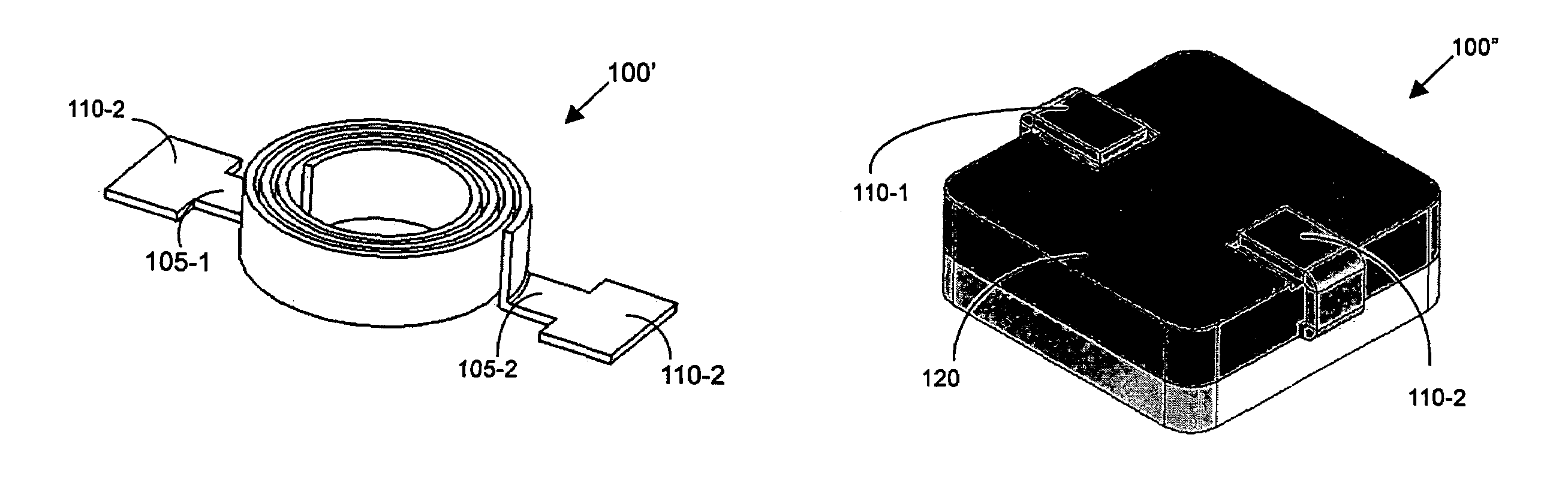
[0027]Referring to FIGS. 2A to 2D for a series of perspective views to illustrate the manufacturing processes of this invention. In FIG. 2A, a conductive flat wire 100 that includes a first terminal extension 105-1 extended from a first end of the flat wire 100 connected to a first terminal plate. The flat ...


PUM

PropertyMeasurementUnit
diameteraaaaaaaaaa
temperature coefficient of resistanceaaaaaaaaaa
diameteraaaaaaaaaa

Abstract

This invention discloses an inductor that includes a conducting wire composed of an alloy having temperature coefficients of resistance (TCR) 700 ppm / ° C. or lower. The inductive coil has a winding configuration provided for enclosure in a substantially rectangular box with a mid-plane extended along an elongated direction of the rectangular box wherein the conducting wire intersecting at least twice near said mid-plane.

Description

[0001]This Patent Application is a Continuous in Part Application (CIP) and claims the Priority Date of a patent application Ser. No. 10 / 937,465 filed on Sep. 8, 2004, now U.S. Pat. No. 7,339,451, by one of the co-inventors of this Application.BACKGROUND OF THE INVENTION[0002]1. Field of the Invention[0003]This invention relates generally to the device configuration and processes for manufacturing inductor coils. More particularly, this invention relates to an improved configuration, process and materials for manufacturing compact inductor coils applicable for accurate current measurements.[0004]2. Description of the Prior Art[0005]For those of ordinary skill in the art, an inductive coil is usually not suitable for current measurement due to the variation of resistance with temperature. Specifically, an inductive coil is generally made with copper coils. Since the copper has a relative high temperature coefficient of resistance (TCR), as the current passes through the copper coils,...

Claims


Application Information

Patent Timeline
Patent Type & Authority Patents(United States)
IPC IPC(8): H01F5/00
CPCH01F17/04H01F27/027H01F27/292H01F2017/046H01F2017/048H01F27/255H01F27/2828
Inventor LIU, CHUN-TIAO
Owner CYNTEC
Why Eureka
Try Eureka