Thermally controlled solar reflector facet with heat recovery

a solar reflector and heat recovery technology, applied in the field of solar power plants, can solve the problems of high operating temperature, difficulty in maintaining, and high operating temperature of conventional solar reflectors, and achieve the effect of improving the operation of the concentrator, effectively wasting in the conventional system

Inactive Publication Date: 2010-03-02
SOLARRESERVE TECH
View PDF30 Cites 8 Cited by
  • Summary
  • Abstract
  • Description
  • Claims
  • Application Information

AI Technical Summary

Benefits of technology

[0012]The above and other objectives are provided by a method and high concentration central receiver system in accordance with the present invention. The central receiver system has a plurality of interconnected reflectors coupled to a tower structure at a predetermined height above ground for reflecting solar radiation. A plurality of parabolic concentrators are disposed between the reflectors and the ground such that the concentrators receive reflected solar radiation from the reflectors. The central receiver system further includes a heat removal system for removing heat from the tower-mounted reflectors and an area immediately adjacent the parabolic concentrators. Removing the heat from the area immediately adjacent the concentrators improves operation of the concentrators and provides an additional source of energy that is effectively wasted in conventional systems.
[0013]Further in accordance with the present invention, a reflector for a high concentration central receiver system is provided. The reflector includes a mirror, a facet, and an adhesive compound. The facet has walls defining a coolant channel, where the cooling channel receives a heat conductive fluid. The adhesive compound is disposed between the mirror and the facet such that the mirror is fixed to the facet under compressive stresses. In the preferred embodiment, the glass mirror has a compression stress value such that no part of the glass experiences tensile stresses. Generating compressive stresses in the mirror improves the strength and resistance to breakage because glass has a low tensile strength. Pre-loading the glass in compression thus avoids the most common failure mode for glass.

Problems solved by technology

A particularly difficult aspect of conventional solar reflectors relates to high operating temperatures, cost and breakage.
Specifically, while various facet designs and heat removal systems have been designed for tower reflectors, a number of difficulties remain.
Generally, these mirrors have been shown to be too costly for practical use in high temperature commercial applications.
The conventional design is also prone to breakage, since the glass is held by “clips” such that there are slight stresses built up in the glass under nominal conditions.
For example, high stresses occur (especially when exposed to sand, dust and ice, since these can cause “ratcheting”) when the glass expands and contracts due to exposure to diurnal cycles of high concentration irradiance, with high temperatures, followed by little or no irradiance and relatively cool temperatures.
The resultant expansion and contraction, with metal joints used to hold the glass securely for good alignment, can result in high local stresses and breakage.
Since the glass is not otherwise constrained, it can fall, causing a significant hazard to equipment and personnel below.
In particular, the falling glass can damage the high optical quality, relatively high cost Compound Parabolic Concentrators (CPCS) on the ground.
The conventional approach also does not provide for adequate thermal control to prevent ice buildup.
Ice buildup on high structures is a serious problem, since it can greatly increase the structural load, distort and damage the glass mirrors.
If ice forms and falls onto the CPCs, further damage is likely to be caused to the system.
Such supports do not offer the torsional stiffness inherent in geometries such as triangular shapes.
The mass of material required, and the complexity of assembly (as well as cost) are therefore higher than for other geometric shapes.
This heating can cause damage to the mirrors or to the support backing structure.
Furthermore, the optical quality can be degraded by changes in the radius of curvature, increases in the surface slope error, damage to the reflective surface, or warpage.
For example, the “spillage” area immediately adjacent the concentrators is also a considerable source of heat.
As already mentioned, extreme cold or ice buildup can also cause problems.
These problems include warpage of the facet or its support structure, changes in the facet cant angle, build-up of extremely high loads on the structure, or cracks in the glass.
Also, for certain applications, the mirror assembly must be very light weight, and in some applications the mirror must be mounted in a location where access is difficult.

Method used


Image

  • Thermally controlled solar reflector facet with heat recovery
  • Thermally controlled solar reflector facet with heat recovery
  • Thermally controlled solar reflector facet with heat recovery

Examples


Embodiment Construction

[0036]Reference will now be made in detail to the present preferred embodiments of the invention, examples of which are illustrated in the accompanying drawings. Wherever possible, the same reference numerals will be used throughout the drawings to refer to the same or like parts.

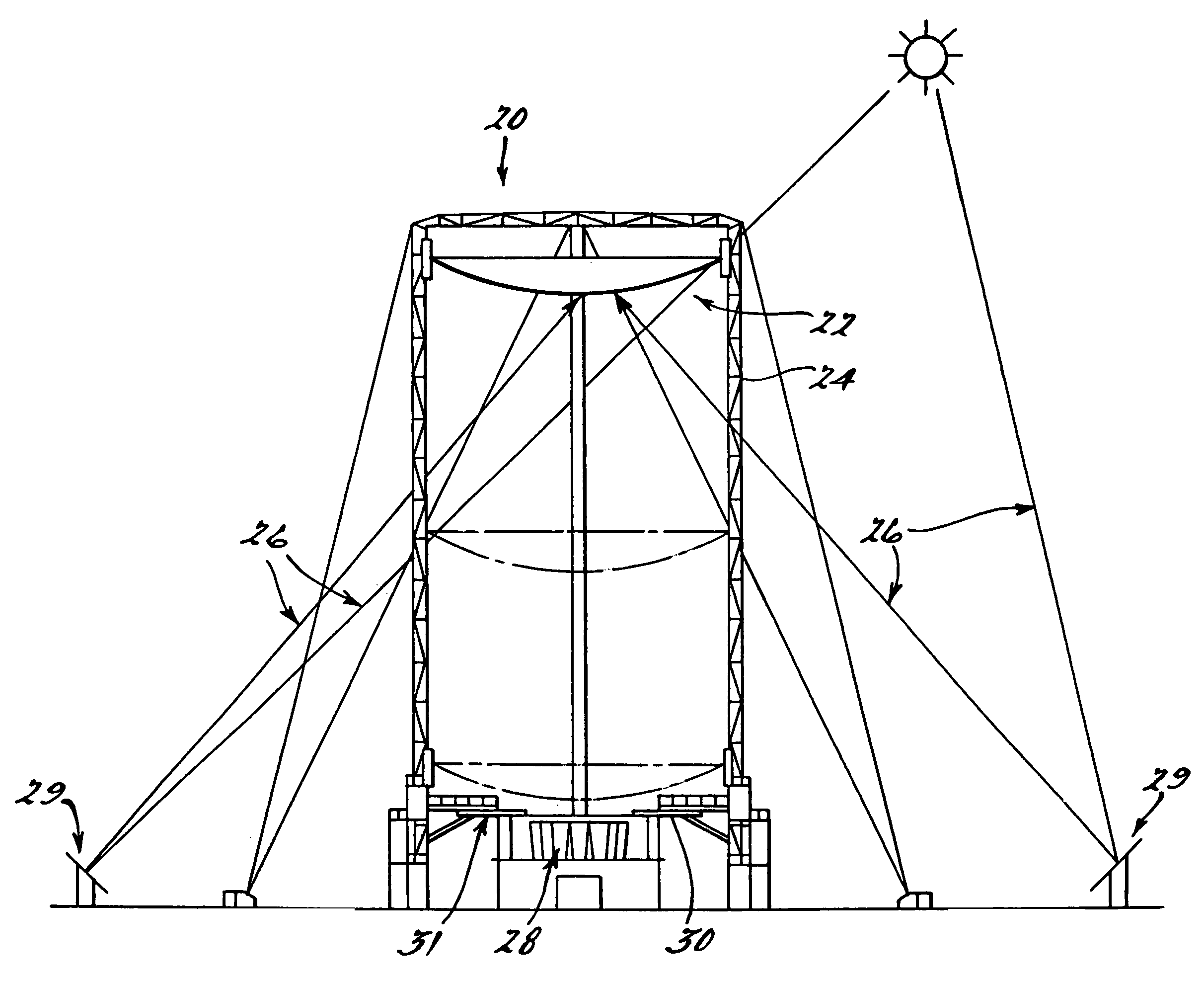
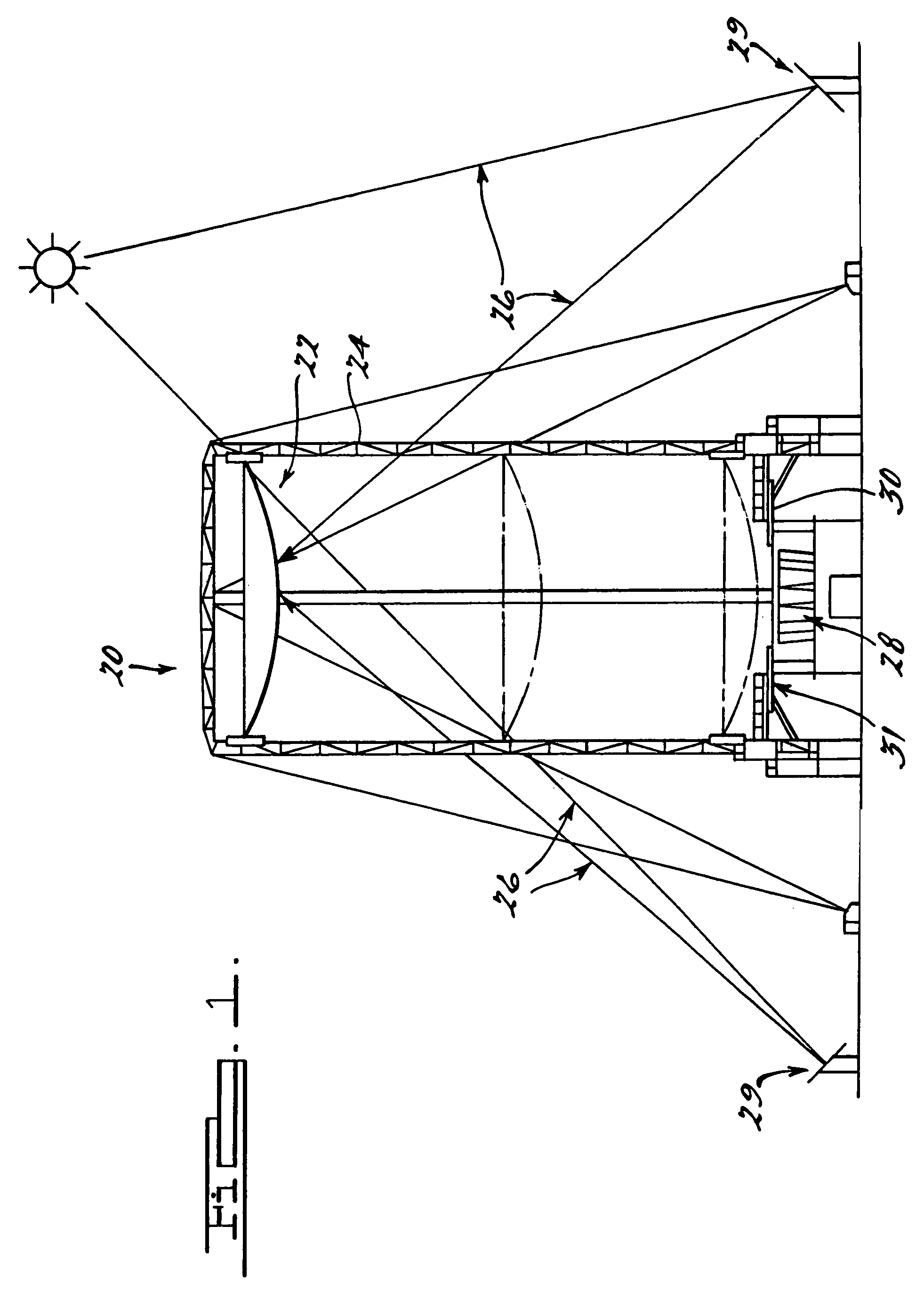
[0037]Turning now to FIG. 1, a high concentration central receiver system 20 is shown in greater detail. The receiver system 20 has a plurality of interconnected reflectors 22 (or reflector assemblies) coupled to a tower structure 24 at a predetermined height above ground for reflecting solar radiation 26. A plurality of concentrators 28 are disposed between the reflectors 22 and the ground such that the concentrators 28 receive reflected solar radiation from the reflectors 22. A heat removal system 30 (or spillage collector) removes heat from the reflectors 22 and an area immediately adjacent the concentrators 28.

[0038]Thus, FIG. 1 shows the basic beam down optics central receiver concept with the reflecto...


PUM


Abstract

A high concentration central receiver system and method provides improved reflectors and a unique heat removal system. The central receiver has a plurality of interconnected reflectors coupled to a tower structure at a predetermined height above ground for reflecting solar radiation. A plurality of concentrators are disposed between the reflectors and the ground such that the concentrators receive reflective solar radiation from the reflectors. The central receiver system further includes a heat removal system for removing heat from the reflectors and an area immediately adjacent the concentrators. Each reflector includes a mirror, a facet, and an adhesive compound. The adhesive compound is disposed between the mirror and the facet such that the mirror is fixed to the facet under a compressive stress.

Description

CROSS-REFERENCE TO RELATED APPLICATIONS[0001]This application is a divisional of U.S. patent application Ser. No. 09 / 879,363 filed on Jun. 12, 2001. The disclosure of the above application is incorporated herein by reference.BACKGROUND OF THE INVENTION[0002]The present invention relates to solar power plants. More particularly, the invention relates to a high concentration central receiver system having improved reflectors and a unique heat removal system.[0003]As concerns over the environment, the deterioration of fuel sources, and energy efficiency continue to increase, solar power plants have become the subject of worldwide attention. In the development of solar power plants, high concentration central receiver systems have demonstrated a relatively high level of usefulness and are therefore quite popular. The conventional solar central receiver system has a “tower top” configuration in which a field of heliostats reflect sunlight onto a receiver mounted on a tower structure. The...

Claims


Application Information

Patent Timeline
Patent Type & Authority Patents(United States)
IPC IPC(8): F24J2/28F24S20/20F24S10/80F24S23/30F24S23/70F24S23/79
CPCF24J2/5264B32B37/144F24J2/07F24J2/08F24J2/1057F24J2/18F24J2/4625B32B37/06B32B2311/24B32B2315/08B32B2551/08F24J2002/0038Y02E10/41Y02E10/47B32B37/12F24S80/30F24S23/70F24S23/79F24S20/20F24S40/55F24S23/82F24S25/70F24S2020/10F24S23/30Y02E10/40
Inventor BLACKMON, JR., JAMES BJONES, NELSON EDRUBKA, ROBERT E
Owner SOLARRESERVE TECH
Why Eureka
Try Eureka