Control device of a stopper-rod

a control device and stopper technology, applied in the direction of heat treatment process control, manufacturing converters, liquid dispensing, etc., can solve the problems of low response time, complex parts, and inability to precisely control the operating position, and achieve the effect of reducing overall dimensions and high operating speed of the stopper

Inactive Publication Date: 2010-03-02
DANIELI & C OFF MEC SPA
View PDF6 Cites 0 Cited by
  • Summary
  • Abstract
  • Description
  • Claims
  • Application Information

AI Technical Summary

Benefits of technology

[0008]A primary object of the present invention is to produce a control device of a stopper-rod, or simply stopper, which allows high operating speed of the stopper, with reduced overall dimensions.
[0009]Another object is to eliminate the play of all components involved in movement of the stopper, thus allowing greater precision and more precise regulation of the flow of steel. The absence of play also allows the position of the stopper-rod to be regulated using an angular sensor positioned on the motor means, advantageously a resolver. This sensor, integrated into the motor means, is notoriously much less delicate than a linear transducer and therefore less subject to malfunctioning.
[0010]A further object is to produce a device which does not require maintenance. Therefore, to attain the objects set forth above, the present invention provides a control device for a stopper according to the characteristics claimed in claim 1. Advantageously, the presence of a minimum number of moving parts between the lifting rod and the motor and the absence of play between said parts allow low response times and precise control of movement.
[0011]The device of the invention also has a high level of rigidity which allows precise movement transmission.

Problems solved by technology

Notwithstanding the type of motor, the response time is limited by the mechanical play of the system, which prevents precise control of the operating position.
The disadvantages of these devices are:
low response times; complexity of the parts; higher number of mechanical components that produce play, with consequent imprecise control of regulation and the need to perform maintenance on the system.
Given the presence of play, the position of the stopper-rod must also be measured by means of a linear transducer directly on the stopper arm, said sensor typically being delicate and subject to malfunctioning.
On the other hand, hydraulic or hydrodynamic devices allow better response compared to electromechanical devices; however, they require the presence of control units and valves which require a certain amount of space and imply a noteworthy increase in costs.
Also in this case the presence of a high number of moving parts subject to wear between the lifting rod, which regulates upward or downward movement of the stopper, and the servomotor, and the presence of an oil filtering system, which must be kept constantly efficient, make frequent maintenance necessary.
Moreover, a costly system of valves is provided to control the flow of the hydraulic fluid to, from and between the opposite sides of the piston.

Method used


Image

  • Control device of a stopper-rod
  • Control device of a stopper-rod
  • Control device of a stopper-rod

Examples


Embodiment Construction

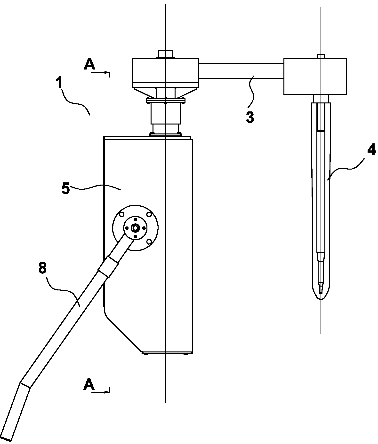
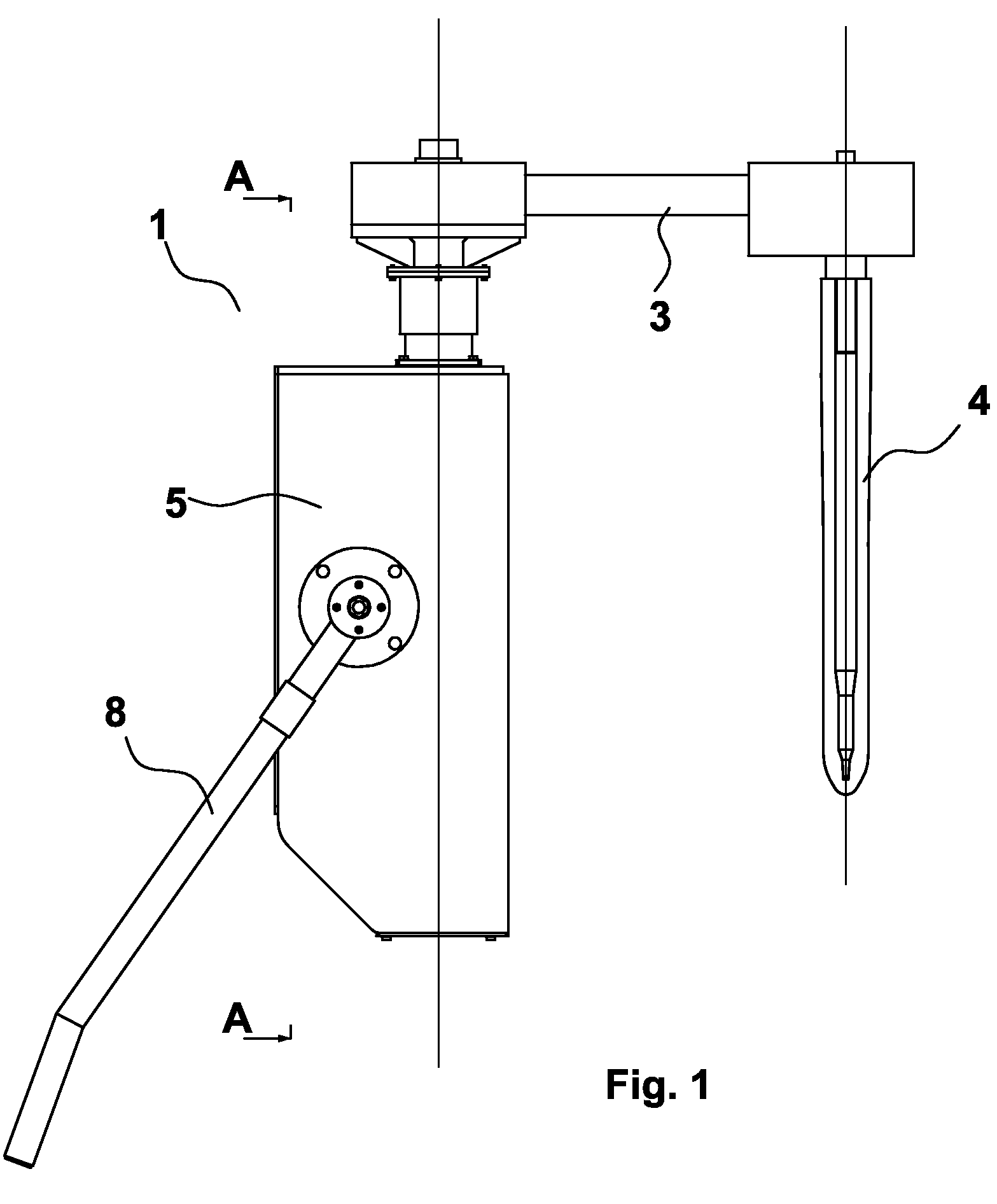
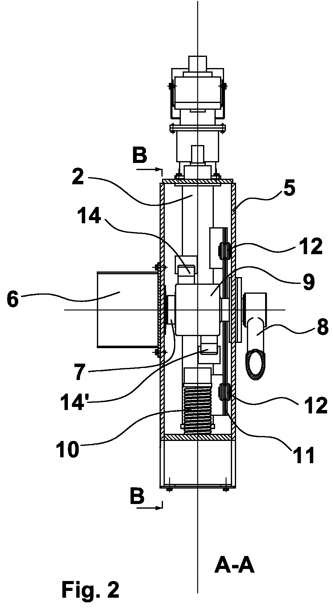
[0017]With reference to the figures, a control device for a stopper, indicated as a whole with the reference numeral 1, is represented. This device comprises:[0018]motor means 6,[0019]a drive shaft 7,[0020]motion conversion means 14, 14′;[0021]a lifting and lowering rod or stem 2;[0022]a connection element or arm 3.

[0023]The motor means, for example a planetary gearmotor 6, impart motion to the lifting and lowering rod or stem 2, housed in a retaining frame 5. Said gearmotor 6, or motor, has reduced dimensions, especially the axial dimensions; it has low inertia; reduced play; high rigidity and high power.

[0024]The direct drive gearmotor 6 is keyed onto one end of the drive shaft 7, essentially horizontal and passing through the retaining frame 5, while at the other end thereof an extractable lever 8 is fitted for manual control of the rod 2. Both the motor and the lever for manual control are outside the retaining frame.

[0025]Advantageously, the suspension bearing of the shaft does...


PUM

PropertyMeasurementUnit
flexibleaaaaaaaaaa
elasticaaaaaaaaaa
pouring speedsaaaaaaaaaa

Abstract

Control device for a stopper-rod to regulate the outflow of liquid metal through a calibrated hole of a pouring receptacle comprising motor means, suitable to operate lifting and lowering means (2) of the stopper (4) by means of first driving means (7) and second driving means (14, 14′), the latter being suitable to convert a rotating motion into a translational motion, wherein the second driving means are flexible longitudinal elements and are fixed at a first end thereof to lifting and lowering means and a second end thereof to an anchor element (9), integral with the first means.

Description

FIELD OF THE INVENTION[0001]The present invention relates to a control device of a stopper, in particular of a stopper-rod used to regulate the outflow of liquid steel through a ladle or a tundish.PRIOR ART[0002]The stopper-rod, or simply stopper, is the device which interacts with a calibrated hole or nozzle to regulate the outflow of liquid steel through a ladle or a tundish. Continuous regulation of the stopper takes place as a function of the level of steel in the ingot mould which is continuously monitored by a radioactive sensor that sends a signal to a programmable logic controller which, in turn, controls the motor of the device to control or move the stopper. The control device must control the stopper so as to continuously guarantee a stable meniscus in the pouring receptacle, and therefore it must allow a high operating speed of said stopper, especially for high pouring speeds. Two types of control device are known: one electromechanical and one hydraulic. Having defined ...

Claims


Application Information

Patent Timeline
Patent Type & Authority Patents(United States)
IPC IPC(8): B22D41/20
CPCB22D41/20
Inventor POLONI, ALFREDODE LUCA, ANDREADAVID, CLAUDIO
Owner DANIELI & C OFF MEC SPA
Why Eureka
Try Eureka