
Extruder system and cutting assembly

a cutting assembly and extruder technology, applied in the field of extruder systems and cutting assemblies, can solve the problems of adversely affecting a chemical reaction, inability to accurately give the correct dosage to the patient, and the size of the catalyst can affect the reaction rate, so as to improve the durability of the die plate and/or the extruder/die insert, improve the ease of use of the extruder/die, and improve the throughput of the extruder

Active Publication Date: 2010-03-09
JMP INDS
View PDF65 Cites 7 Cited by
  • Summary
  • Abstract
  • Description
  • Claims
  • Application Information

AI Technical Summary

Benefits of technology

"The present invention relates to extrusion hardware, particularly extruder plates, extruder / die inserts, wiper blades, auger blades, and cutting assemblies. The invention aims to improve the throughput, durability, ease of use, and quality of extruded materials. The invention provides specially designed extruder plates and extruder / die inserts that can improve throughput, reduce wear rate, and improve the quality of the material extruded. The invention also includes an improved wiper blade that can direct material into the extruder plate and reduce the accumulation of material around the openings in the extruder plate. Overall, the invention improves the efficiency and effectiveness of extrusion systems and reduces waste."

Problems solved by technology

A pill that has been cut too large or a too small may result in the incorrect dosage being given to the patient.
Likewise, in the catalyst industry, the size of the catalyst can affect the rate of reaction that takes place when using the catalyst.
An extruded catalyst that is cut too large or too small could adversely affect a chemical reaction that involves the use of the catalyst.
Due to the hardened or less formable nature of the material, the material can become stuck in the one or more openings, thereby resulting in plugging or clogging the one or more openings.
The clogging or plugging of one or more of the extruder plates and / or extruder / die inserts can also affect the pressure at which the material is extruded through the remaining unclogged openings.
The increased length of the cut product can result in an unacceptable product due to the unacceptably long product length, thus reducing the yield of acceptable products.
The increased pressure on the material can also adversely affect the extruded material (e.g., adversely breaking down chemical bonds or structures, unacceptably increasing the heat applied to the material thereby resulting in adverse chemical reactions or structural formations, etc.).
Such adverse effects on the extruded material can result in the material being unacceptable for its end use, even if the cut length is within an acceptable range.

Method used


Image

  • Extruder system and cutting assembly
  • Extruder system and cutting assembly
  • Extruder system and cutting assembly

Examples


Embodiment Construction

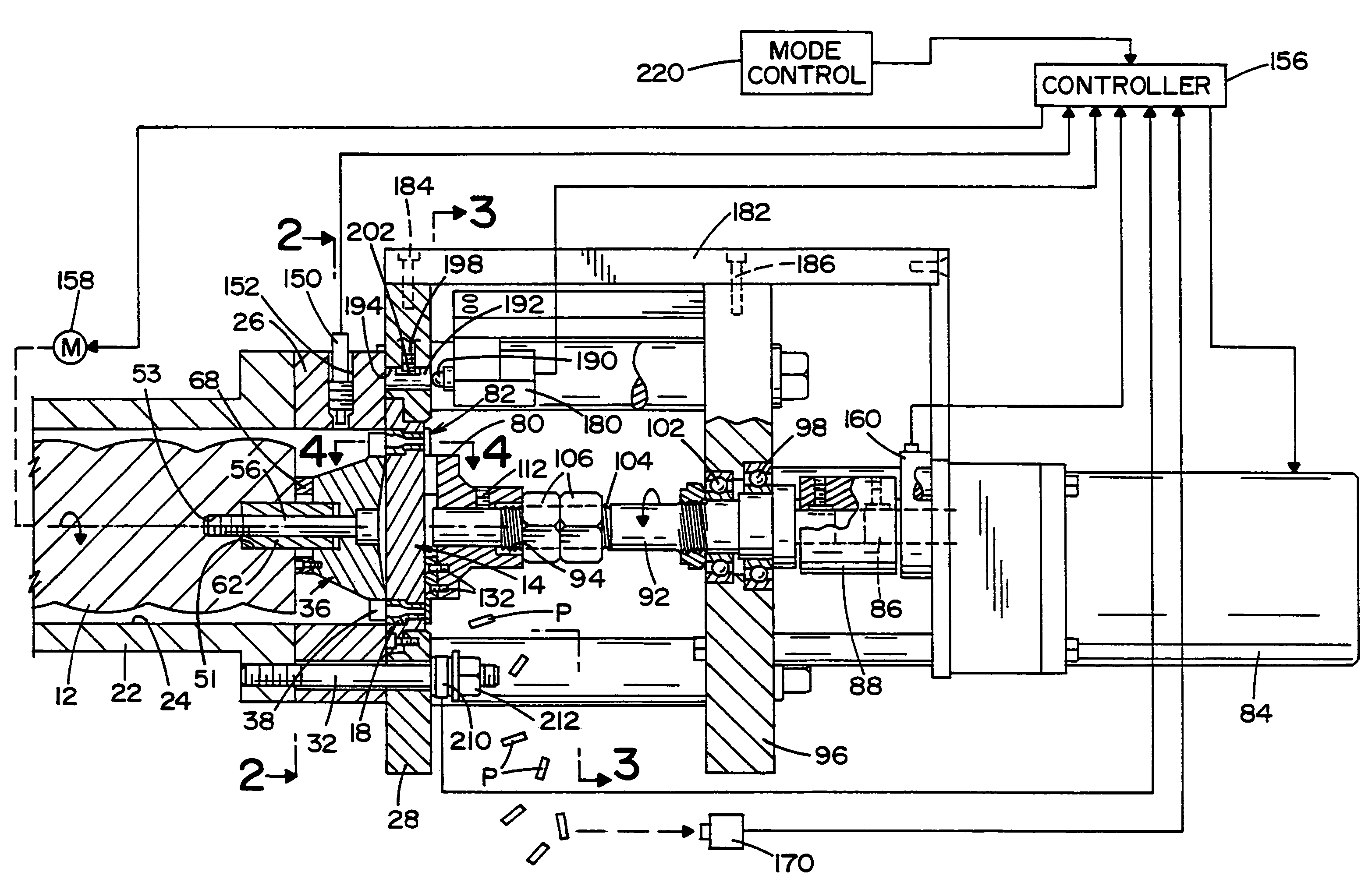
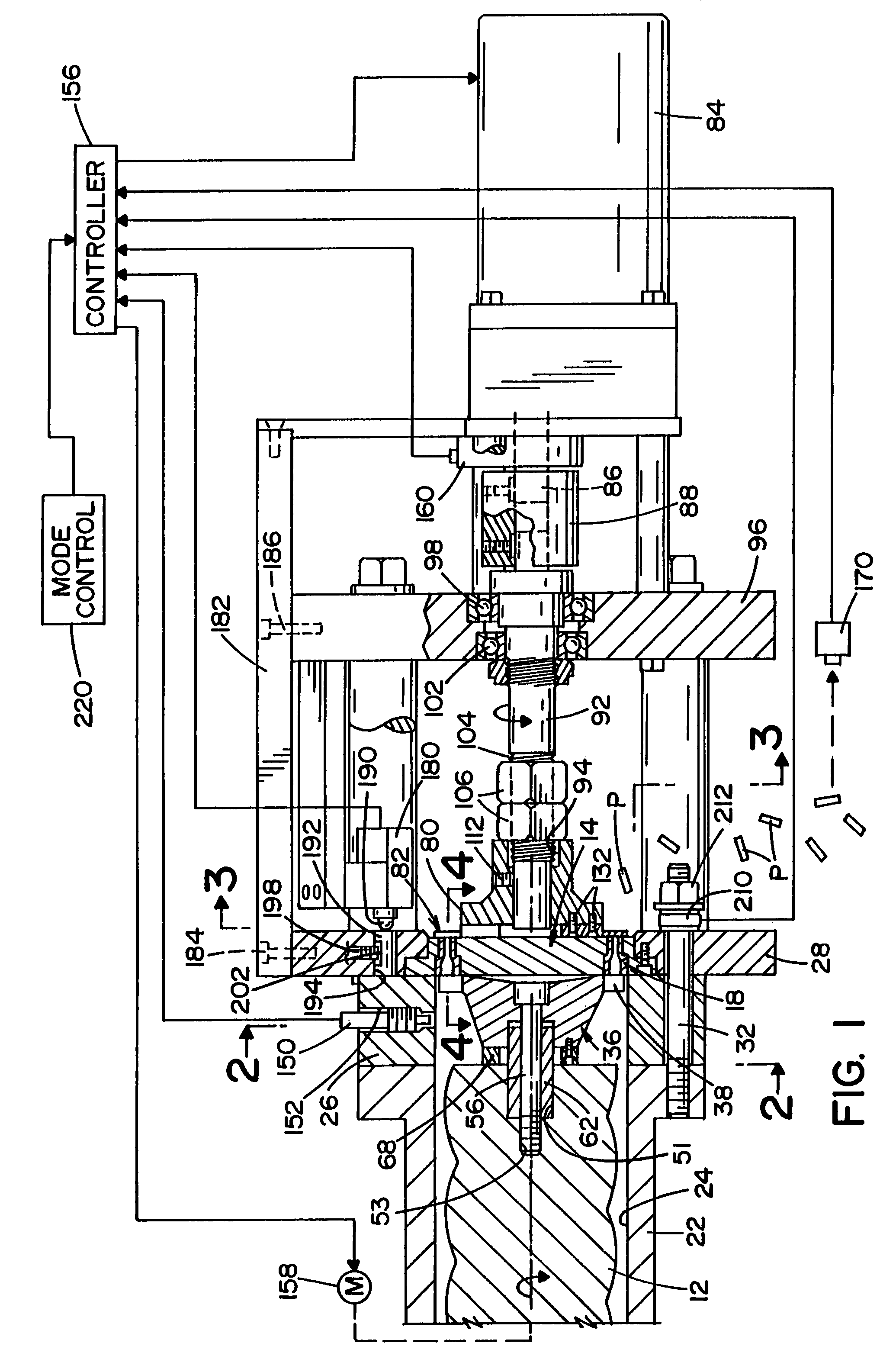
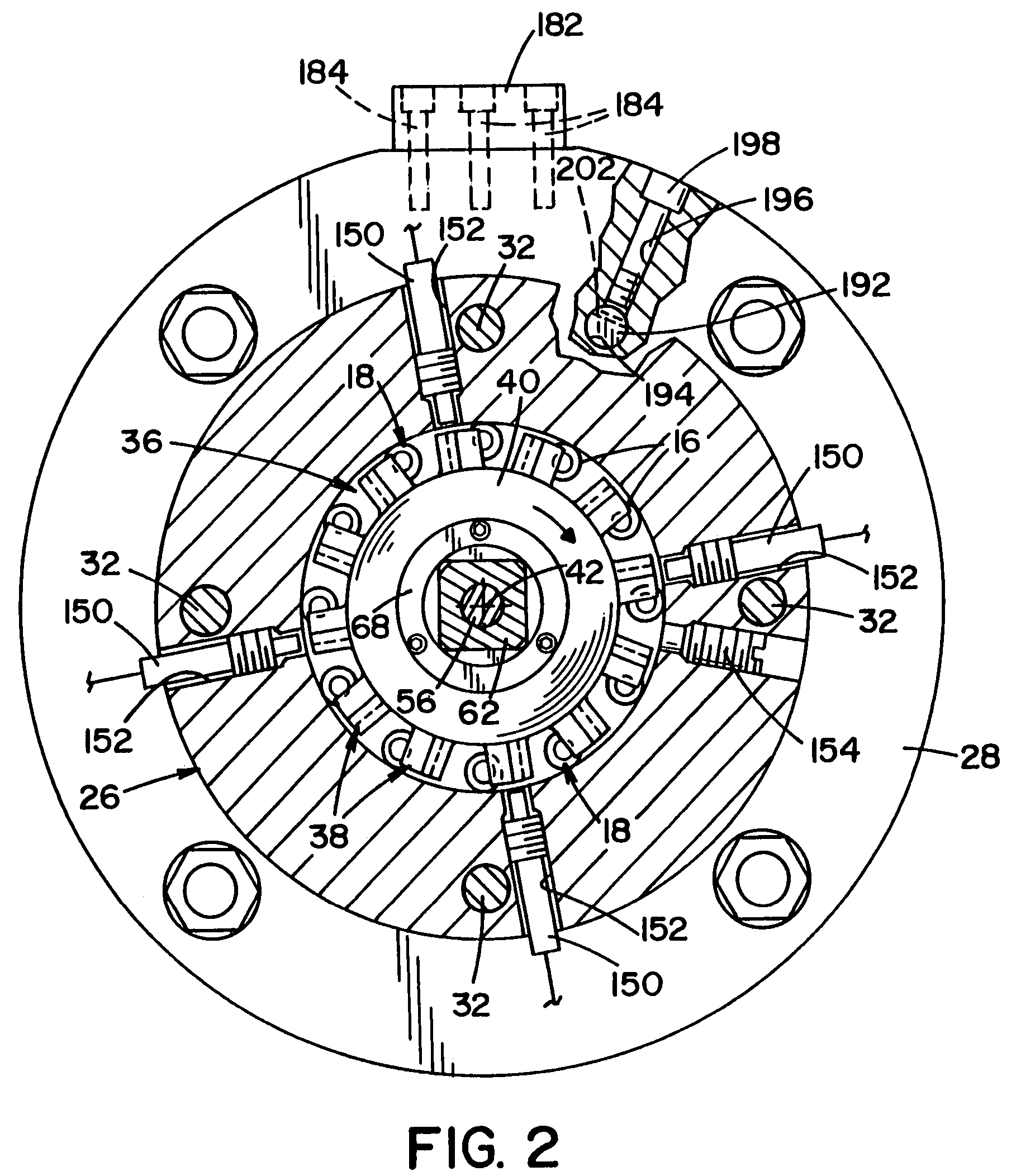
[0084]Referring now to the drawings wherein the showing is for the purpose of illustrating preferred embodiments of the invention only and not for the purpose of limiting the same, FIG. 1 illustrates one non-limiting configuration of an extruder system and cutter assembly in accordance with the present invention. Specifically, FIG. 1 illustrates a cross-section view of the front end portion of an extruder system and the cross-section view of a cutter assembly. With reference to the extruder system ,there is illustrated a portion of an auger blade 12 that is designed to move material, not shown, to be extruded toward an extruder plate 14. The extruder plate 14 is illustrated as having a plurality of die openings 16 that are each designed to receive a die / extruder insert 18. The material that is transported by the auger blade is designed to become an extruded product such as, but not limited to, a catalyst. As can be appreciated, the present invention can be used to form many types of...


PUM

PropertyMeasurementUnit
distanceaaaaaaaaaa
distanceaaaaaaaaaa
distanceaaaaaaaaaa

Abstract

An extruder system and a cutting assembly for cutting a material extruded from an extruder plate.

Description

[0001]This patent application is a continuation-in-part of U.S. patent applications Ser. No. 11 / 062,220 filed Feb. 18, 2005 now abandoned, which claims priority on U.S. provisional patent application Ser. No. 60 / 548,693, filed Feb. 27, 2004, both of which are incorporated herein by reference. This patent application is also a continuation-in-part of PCT Application Serial No. PCT / US2006 / 005751 filed Feb. 17, 2006, which in turn claims priority on U.S. Pat. applications Ser. No. 11 / 062,220 filed Feb. 18, 2005 now abandoned; U.S. patent application Ser. No. 29 / 242,613 filed Nov. 10, 2005 now U.S. Design Pat. D550,259; U.S. patent application Ser. No. 29 / 242,779 filed Nov. 15, 2005 now abandoned; and U.S. patent application Ser. No. 29 / 242,881 filed Nov. 15, 2005 now abandoned, all of which are incorporated herein by reference. This patent application is also a continuation-in-part of U.S. patent application Ser. No. 29 / 263,182 filed Jul. 14, 2006 now U.S. Design Pat. D544,005, which i...

Claims


Application Information

Patent Timeline
Patent Type & Authority Patents(United States)
IPC IPC(8): B29C47/30B29B9/10B29C48/345B29C48/92
CPCA23P1/12B21C35/02B21C35/04B29C47/92B29B9/06B26D1/28B26D5/00A23P30/20B29C48/92B29C2948/92209B29C2948/92409B29C2948/92704B29C2948/92019B29C2948/92514B29C2948/92552B29C2948/92638B29C2948/92904B29C2948/92923
Inventor PINCHOT, JAMES M.
Owner JMP INDS
Learn More