Method and device for making a composite plate

a composite plate and method technology, applied in the field of composite plate making methods and devices, can solve the problems of high cost of machines, inability to use extrusion, and high production costs of films, and achieve the effect of reducing the “marking” effect and improving the adhesion of the coating layer

Inactive Publication Date: 2010-03-09
OCV INTELLECTUAL CAPITAL LLC
View PDF11 Cites 1 Cited by
  • Summary
  • Abstract
  • Description
  • Claims
  • Application Information

AI Technical Summary

Benefits of technology

[0045]The pressure exerted in the compression device makes it possible to compact the web of yarns and make the coating layer uniform, especially by giving it a constant thickness, the structure obtained then being set by cooling.
[0054]Firstly, they constitute a means of reducing the “marking” effect of the yarns present on the surface of the reinforced matrix, by forming an additional layer whose thickness may be regulated according to the desired result.
[0055]These structures also help to improve the adhesion of the coating layer to the reinforced matrix—in certain cases, the adhesion can be effected by their agency alone.
[0057]Finally, they produce a “barrier” effect, especially by preventing interpenetration of the coating layer and the reinforced matrix in the final sheet, and also give said sheet fireproofing, waterproofing and thermal and / or acoustic insulation properties.
[0069]The sheets generally have a thickness of 1 to 10 mm, preferably 1 to 6 mm, are easy to cut and exhibit good mechanical properties, in particular good impact (stone-chip, hailstone) resistance. The sheets obtained are also rigid, but may have, where appropriate, sufficient flexibility to be able to be collected and stored in wound form. They may also be used for the thermoforming and molding of parts made of composites.
[0072]The composite sheets have the advantage of being able to be welded without external addition of material, and are capable of being molded, especially by thermoforming. Furthermore, it is easy to repair the coating when it has been damaged, simply by depositing the coating powder, optionally dispersed in a liquid or in mastic form, and then heating it. They may also be easily recycled in the form of granules or small pieces, for injection molding or compression molding.

Problems solved by technology

It is difficult and also very expensive to produce such films, as the production requires machines that are specially adapted to these large widths.
For widths greater than 2 meters, it is not conceivable to use extrusion since the cost of the machine is much too high.
With reels, there are additional problems associated with production (size of the reels, quality of the film), with storage and with the requirement to have a specific film for each type of panel, especially as regards the color.
However, the final panel is unsatisfactory as marks remain visible where the films are joined together.
The nature of the material used does not allow correct bonding of the paint when it is applied directly.
Although this method allows great freedom in the choice of color, it also has drawbacks.
Such a level of performance is not achieved with chopped yarns, particularly short chopped yarns, as they all do not lie in the plane of the web under the compression effect, some of them retaining an orientation perpendicular to said plane.

Method used


Image

  • Method and device for making a composite plate
  • Method and device for making a composite plate

Examples


example 1

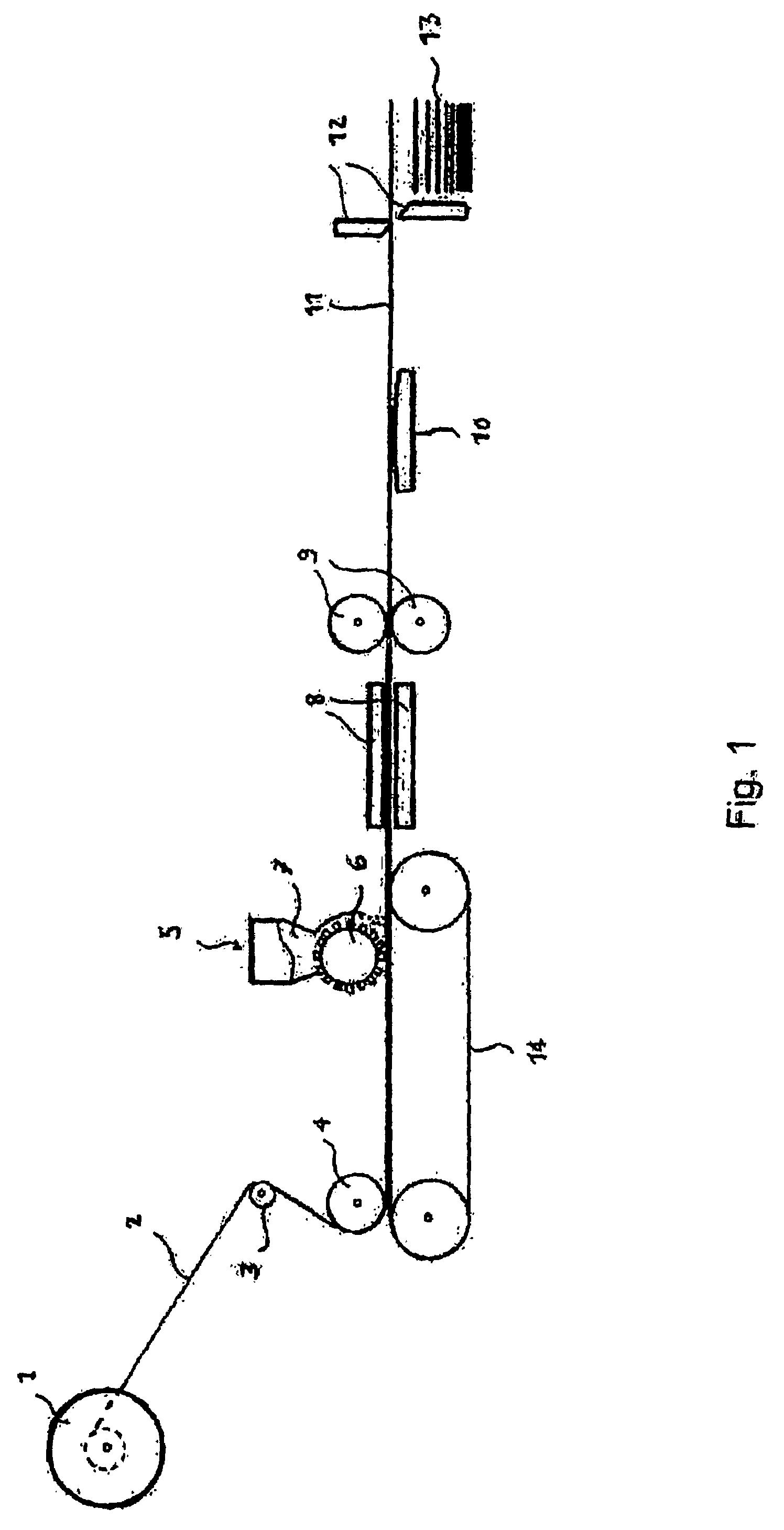
[0091]The installation described in FIG. 1 was used to manufacture a composite sheet 1.5 m in width and 1.5 mm in thickness, consisting of 60% glass by weight and 40% polypropylene by weight.

[0092]Assemblies of continuous yarns, 750 g / m2 in weight and 1.5 m in width, comprising, as warp and as weft, intermingled yarns formed from 1870-tex intermingled rovings containing 60% glass by weight and 40% polypropylene by weight, were used, the yarns being bound together in the weft direction by stitching-knitting with a polypropylene binding yarn.

[0093]Two assemblies coming from two reels were superposed on the conveyor belt and a powder of a polyolefin-based thermoplastic alloy (Plascoat® Talisman sold by Plascoat) was applied to the top side of the assembly in an amount of 500 g / m2. The assembly, running at a speed of 1.5 m / minute, was heated between the infrared radiation panels (length: 1 m; temperature: 200° C.) and then passed between the rolls (diameter: 300 mm; temperature: 40° C.;...

example 2

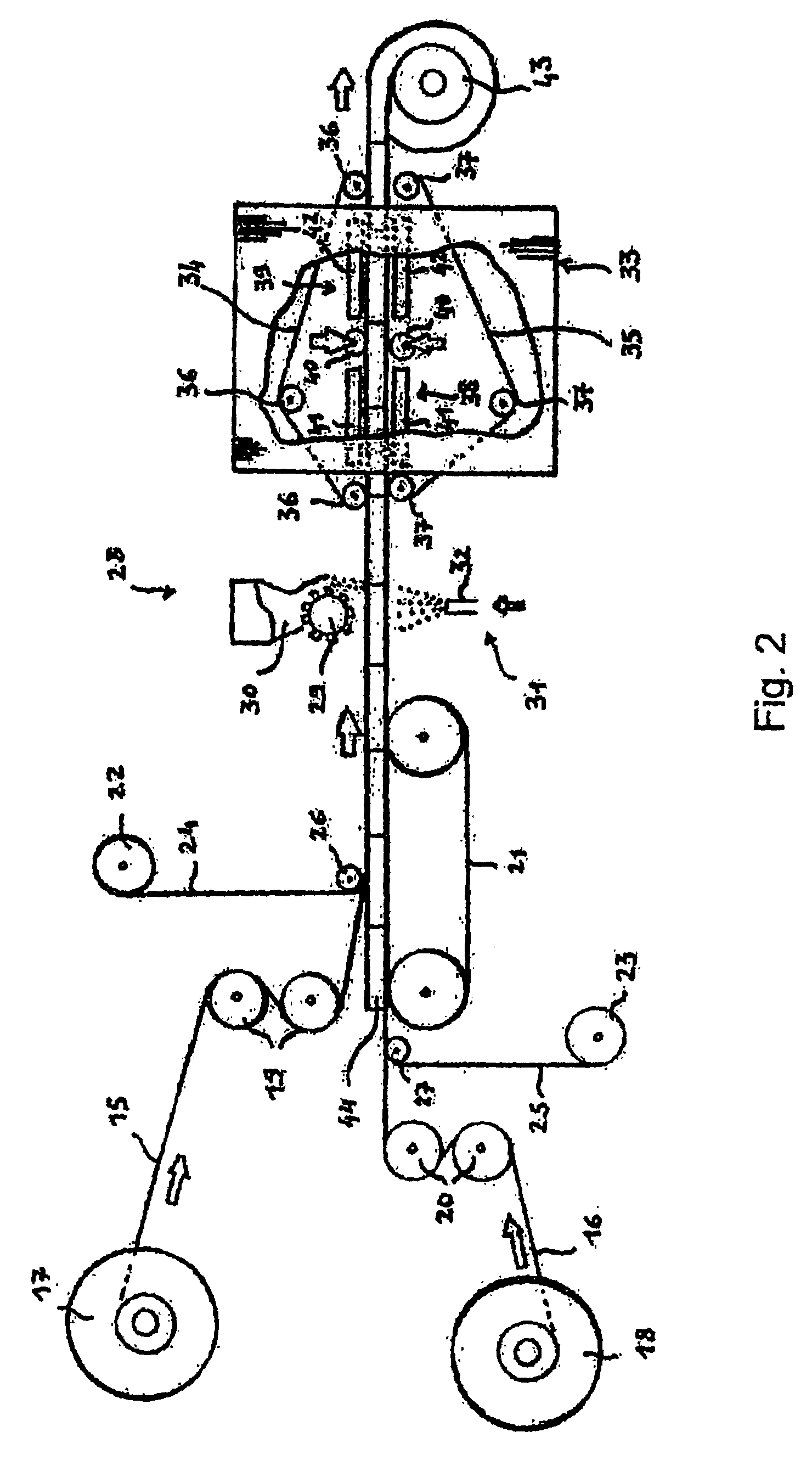
[0095]The installation of FIG. 2 was used.

[0096]A “jet fluid”-bonded 70 g / m2 polyester veil (reference NLC 10 / 701 sold by PGI) was deposited on two 745 g / m2 wovens formed from 1870 tex intermingled rovings containing 60% glass by weight and 40% polypropylene by weight, bulk-colored black, in a 2×2 twill, 1.5 m in width, and the powder of thermoplastic alloy of example 1 was applied in an amount of 500 g / m2. The assembly was introduced into a double belt press comprising a heated zone at 200 °C., a two-roll calender (pressure: 1.5 bar (0.15 MPa)) and a cooling zone at 20° C. The press operated at a speed of 2 meters per minute.

[0097]A sheet 1.5 mm in thickness comprising a uniform glossy coating layer, white in color, was obtained.

example 3

[0098]The conditions of example 1 were used. A 50 g / m2 glass veil was deposited on a 1485 g / m2 woven formed from 1870 tex interminged rovings containing 60% glass by weight and 40% polypropylene by weight, in a 2×2 twill with sides of 1.5 m, and the powder of thermoplastic alloy of example 1 was applied in an amount of 500 g / m2.

[0099]The assembly, running at a speed of 1.5 m / min, was heated between the infrared radiation panels (temperature: 220° C.) and then passed into the calender.

[0100]The composite sheet obtained had a thickness of 1.5 mm. It was cut up and heated to 220° C. for 1 minute in an infrared oven, it was then transferred into a press, consisting of a rectangular mold and a countermold regulated to 60° C., and subjected to a 40 bar (4 MPa) pressure for 1 minute.

[0101]After demolding, a box 150 mm in width, 200 mm in length and 20 mm in height, having a uniform coating and no material distribution defect, was obtained.


PUM

PropertyMeasurementUnit
thicknessaaaaaaaaaa
thicknessaaaaaaaaaa
widthaaaaaaaaaa

Abstract

A process for manufacturing composite sheets includes steps of:continuously depositing a web of yarns, in the form of a mat of continuous yarns, a woven, a knit or an assembly of continuous non-interlaced yarns on a moving substrate;depositing a powder of an organic material capable of forming a coating layer under the action of heat on at least one side of said web;heating the web coated with the powder to a temperature sufficient to melt the powder;compressing and cooling the web so as to form a composite strip; andcutting the strip in the form of sheets or winding the strip up on a rotating support.

Description

[0001]This application is a 371(c) of PCT / FR03 / 03648, filed on Dec. 10, 2003, which claims priority to French application number 02 / 16043, filed on Dec. 13, 2002, the text of which is herein incorporated by reference.[0002]The present invention relates to a process and to an installation for the continuous manufacture of a composite sheet comprising a thermoplastic or thermosetting matrix and reinforcing yarns, and a layer of a coating that improves the surface appearance, this sheet being more particularly intended for the production of panels for vehicles or containers for transporting or storing merchandise.BACKGROUND OF THE INVENTION[0003]More precisely, the invention relates to a process, and to the installation allowing its implementation, which consists in applying, to a web of yarns continuously deposited on a moving substrate, a powder of a material capable of reacting under the effect of heat in order to form a coating layer, said web comprising at least one organic, therm...

Claims


Application Information

Patent Timeline
Patent Type & Authority Patents(United States)
IPC IPC(8): B05D1/12B29C37/00B29C70/08B29C70/50
CPCB29C37/0025B29C70/088B29C70/50B29C2043/483Y10T428/249953B29C33/00B29C70/08
Inventor PARDO, PHILIPPELOUBINOUX, DOMINIQUECURIE, ALAIN
Owner OCV INTELLECTUAL CAPITAL LLC
Why Eureka
Try Eureka