Piezoelectric vibrating reed and piezoelectric device

a technology of piezoelectric and vibrating reed, which is applied in the direction of piezoelectric/electrostrictive device details, device material selection, device details, etc., can solve the problems of piezoelectric vibrating reed b>1/b> and temperature characteristics, and achieve good temperature characteristics, enhance impact resistance, and improve temperature characteristics

Inactive Publication Date: 2010-03-09
SEIKO EPSON CORP
View PDF17 Cites 31 Cited by
  • Summary
  • Abstract
  • Description
  • Claims
  • Application Information

AI Technical Summary

Benefits of technology

[0016]An advantage of the invention is to provide a piezoelectric vibrating reed and a piezoelectric device having a good temperature characteristic in fixed miniaturization by preventing a vibration leakage to avoid an adverse effect of a fixed portion and enhance an impact resistance.
[0017]According to an first aspect of the invention, there is provided a piezoelectric vibrating reed, which includes: a base formed of a piezoelectric material and having a predetermined length; a plurality of vibrating arms extended from one side of the base; a support arm extended in a width direction from the other side spaced apart from the one side of the base by a predetermined interval and extended outside the vibrating arms in the same direction as the vibrating arms; and a cut portion formed of the piezoelectric material reduced in its width direction at a location closer to the vibrating arms than a connection portion where the support arms are connected to the base as one body. In this case, a through-hole is also disposed at a location closer to the vibrating arms than the connection portion where the support arms are connected to the base as one body.
[0018]According to the configuration of the first aspect, the vibrating arm which winds and vibrates extends from an end of the base, and the support arm extends from the other end of the base having the predetermined length.
[0019]Accordingly, the change in stress occurring on in the bonded location due to the change in ambient temperature or dropped impact hardly affects the vibrating arms 35 and 36 by having the wound distance from the bonded location of the support arms 61 and 62 to the other end 53 of the base 51 spaced apart from the distance corresponding to the length exceeding the distance BL2 of the base 51, so that the temperature characteristic becomes particularly good.
[0020]In contrast, the vibration leakage from the vibrating arms which wind and vibrate is hardly affected by having the distance to the support arms and which has spaced the base by a predetermined length of the base exceeding the distance BL2. That is, when the length of the base is extremely short, a strong component of the winding vibration is delivered to the whole support arms to make the control difficult, however, according to the present embodiment, such a problem is sufficiently avoided.
[0021]In addition to such operations, the support arms extend in a width direction from the other end of the base as shown in the Figure and extend in the same direction as the vibrating arms outside the vibrating arms, so that the total size can be made to be compact.

Problems solved by technology

However, the piezoelectric vibrating reed 1 which has been small-sized has problems in terms of temperature characteristics as follows.

Method used


Image

  • Piezoelectric vibrating reed and piezoelectric device
  • Piezoelectric vibrating reed and piezoelectric device
  • Piezoelectric vibrating reed and piezoelectric device

Examples


Embodiment Construction

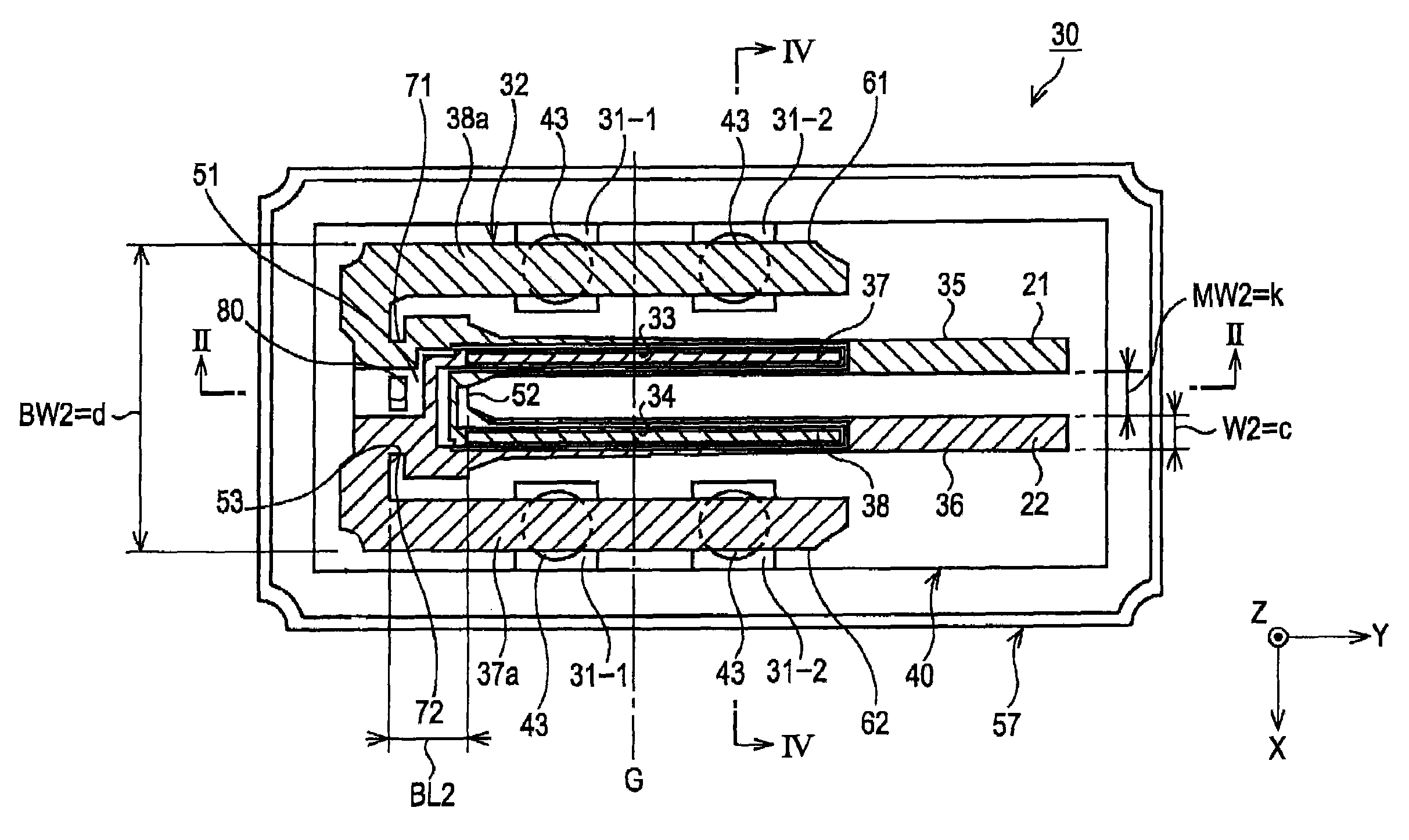
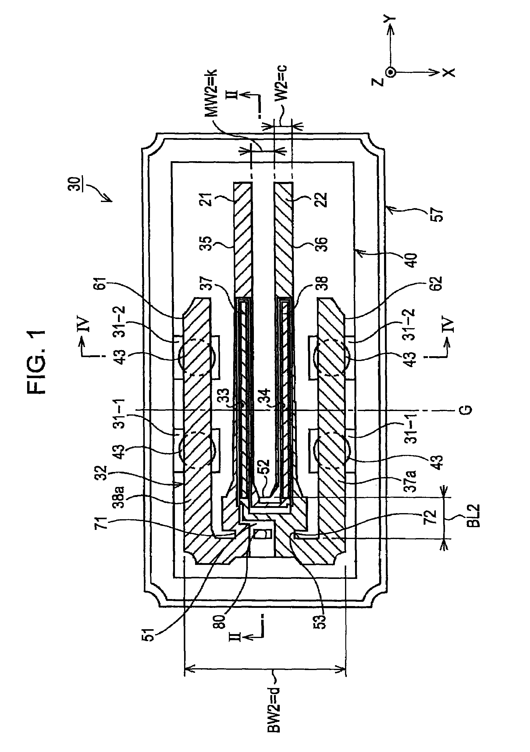
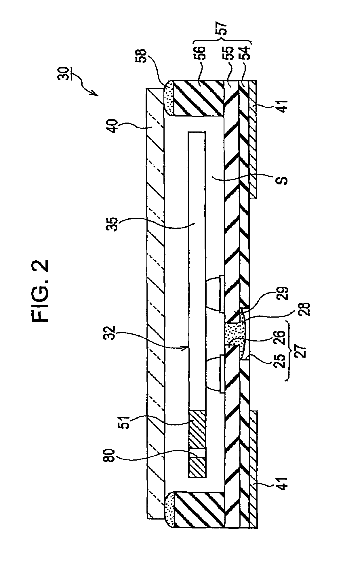
[0052]FIGS. 1 and 2 show an embodiment of the piezoelectric device of the invention, FIG. 1 is its schematic plan diagram, and FIG. 2 is a cross-sectional diagram taken out from the line II-II of FIG. 1. In addition, FIG. 3 is a schematic and enlarged plan diagram for explaining details of the piezoelectric vibrating reed of FIG. 1, and FIG. 4 is a cross-sectional diagram taken out from the line B-B of the vibrating arms of FIG. 1.

[0053]Referring to these Figures, the piezoelectric device 30 is an example of constituting a piezoelectric vibrator, and receives a piezoelectric vibrating reed 32 within a package 57 as a base.

[0054]The package 57 has a rectangular box shape as shown in FIGS. 1 and 2. To detail this, the package 57 is formed by stacking a first substrate 54, a second substrate 55, and a third substrate 56, for example, molding a ceramic green sheet formed of an aluminum oxide as an insulting material to the illustrated shape and then carrying out sintering thereon.

[0055]...


PUM


Abstract

There is provided a piezoelectric vibrating reed, including: a base formed of a piezoelectric material and having a predetermined length; a plurality of vibrating arms extended from one side of the base; a support arm extended in a width direction from the other side spaced apart from the one side of the base by a predetermined interval and extended outside the vibrating arms in the same direction as the vibrating arms; and a cut portion formed of the piezoelectric material reduced in its width direction at a location closer to the vibrating arms than a connection portion where the support arms are connected to the base as one body, wherein a through-hole is also disposed at a location closer to the vibrating arms than the connection portion where the support arms are connected to the base as one body.

Description

BACKGROUND[0001]1. Field of the Invention[0002]The present invention relates to an improvement of a piezoelectric vibrating reed, and a piezoelectric device which has received the piezoelectric vibrating reed within a package or a case.[0003]2. Description of the Related Art[0004]A piezoelectric device such as a piezoelectric vibrator or a piezoelectric oscillator is widely employed in a small-sized information apparatus such as an integrated card (IC) card, a hard disk drive (HDD), a mobile computer, a communication apparatus such as a cellular phone, a car phone, a paging system, or a piezoelectric gyro sensor.[0005]FIG. 9 is a schematic plan view of an example of the piezoelectric vibrating reed which has been employed for the piezoelectric device in the related art.[0006]Referring to FIG. 9, an outer shape of the piezoelectric vibrating reed 1 is formed by etching a piezoelectric material such as quartz, and the piezoelectric vibrating reed 1 has a rectangular base 2 to be mount...

Claims


Application Information

Patent Timeline
Patent Type & Authority Patents(United States)
IPC IPC(8): H01L41/04H01L41/053H01L41/09H01L41/18H01L41/22H01L41/23H01L41/253H01L41/332H03H9/02H03H9/19H03H9/215
CPCH03H9/21H03H9/215H03H9/19
Inventor TANAYA, HIDEO
Owner SEIKO EPSON CORP
Why Eureka
Try Eureka