
Display filter and display device including the same

a display device and filter technology, applied in the direction of optical elements, identification means, instruments, etc., can solve the problems of electronic devices, human health, electronic devices, etc., to prevent external light from entering the panel assembly, and achieve the effect of improving the luminance and contrast ratio of the display device for a bright room condition

Inactive Publication Date: 2010-03-16
ASAHI GLASS CO LTD
View PDF21 Cites 15 Cited by
  • Summary
  • Abstract
  • Description
  • Claims
  • Application Information

AI Technical Summary

Benefits of technology

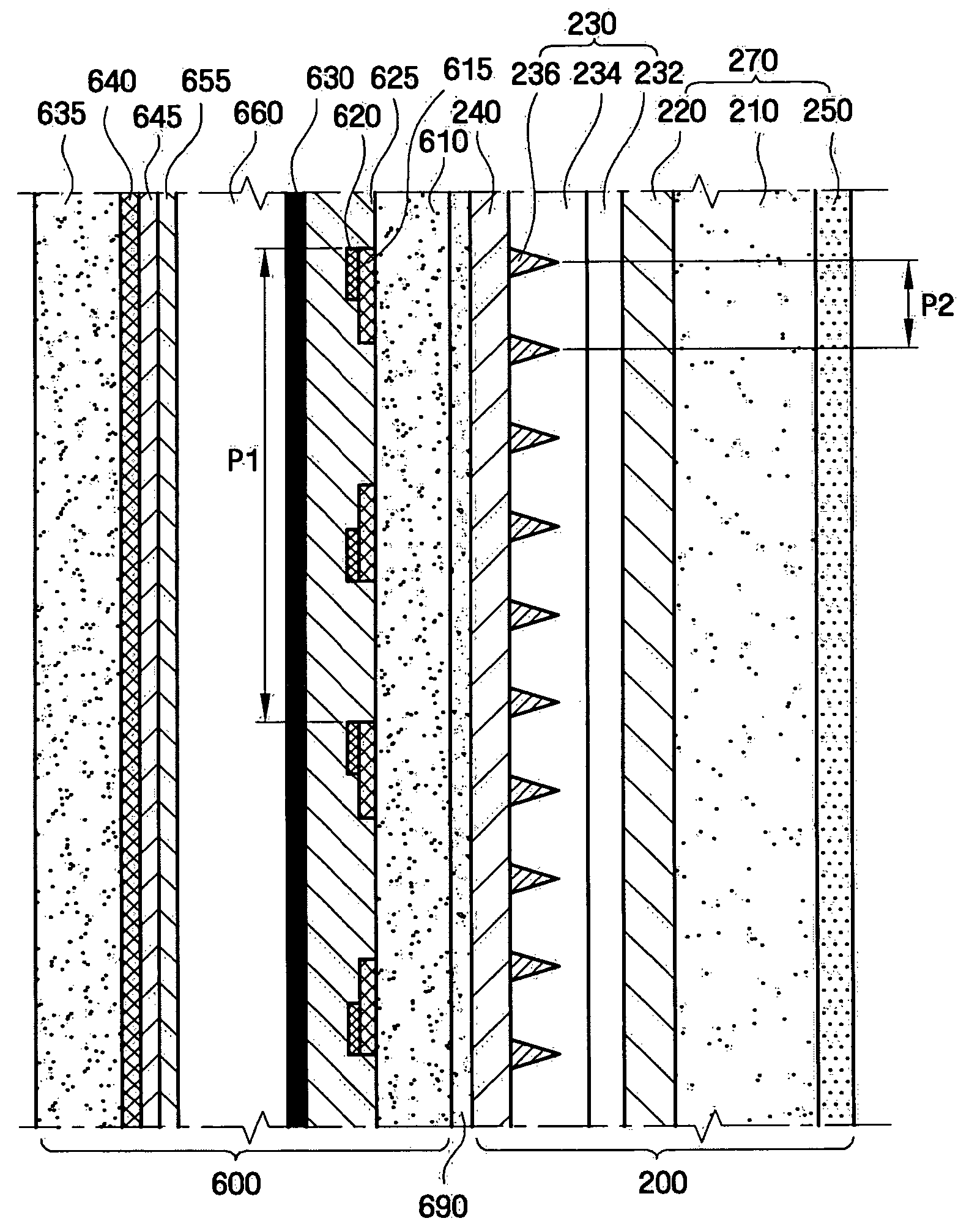
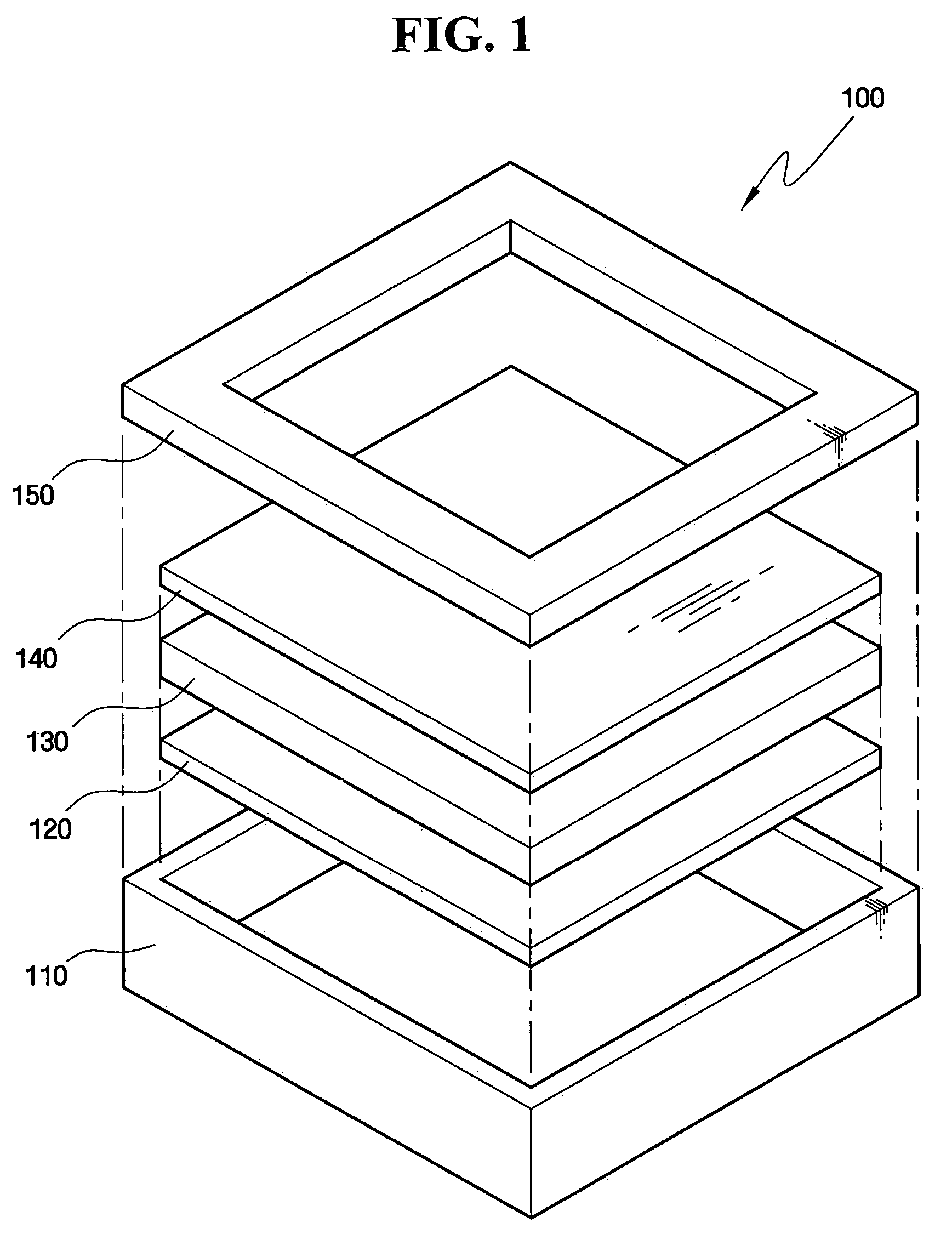
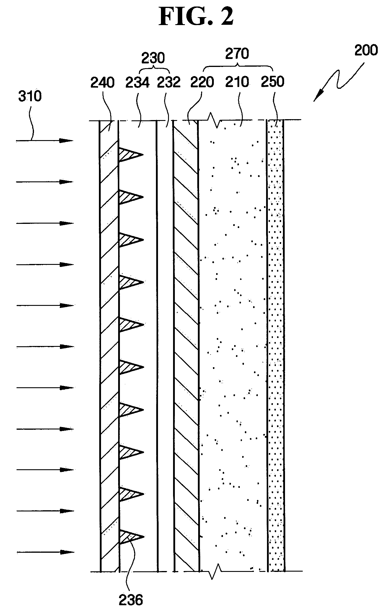
The present invention provides a display filter that improves the luminance and contrast ratio of a display device in a bright room condition. The display filter includes a filter base and an external light-shielding layer made of a transparent resin and wedge-shaped black stripes. The display filter can be used in a display device that includes a panel assembly with a transparent front substrate and a rear substrate, and a plurality of cells between the front and rear substrates. The external light-shielding layer can also have additional functions such as antireflection, EM radiation-shielding, or near-infrared ray wave-shielding.

Problems solved by technology

Despite the above advantages, PDPs have several challenges associated with driving characteristics, including an increase in electromagnetic (EM) radiation, near-infrared (NIR) emission, phosphor surface reflection, and an obscured color purity due to orange light emitted from neon (Ne), helium (He) or xenon (Xe) that is used as a sealing gas.
The electromagnetic (EM) radiation generated by PDPs may adversely affect humans and cause electronic devices, such as wireless telephones or remote controls to malfunction.
Conventional PDP filters cannot, however, prevent external light from entering a panel assembly in a bright room condition.
The external light that entered the panel assembly may undergo interference with light emitted from a discharge cell in the panel assembly, thereby lowering the contrast ratio of a panel operating in a bright room condition, ultimately degrading the image display capability of the PDP.

Method used


Image

  • Display filter and display device including the same
  • Display filter and display device including the same
  • Display filter and display device including the same

Examples


Embodiment Construction

[0026]Advantages and features of the present invention and methods of accomplishing the same may be understood more readily by reference to the following detailed description of preferred embodiments and the accompanying drawings. The present invention may, however, be embodied in many different forms and the detailed description of certain embodiments should not be construed as limiting the invention to those embodiments; rather, these embodiments are provided so that this disclosure will convey the concept of the invention to those skilled in the art. The present invention is defined by the appended claims. Like reference numerals refer to like elements throughout the specification.

[0027]The present invention can be applied to a wide variety of displays including large-size displays such as plasma display panels (PDPs) realizing an RGB color display using matrix pattern pixels, organic light emitting diode displays (OLEDs), liquid crystal displays (LCDs), or field emission display...


PUM

PropertyMeasurementUnit
angleaaaaaaaaaa
visible light transmittanceaaaaaaaaaa
refractive indexaaaaaaaaaa

Abstract

A display filter capable of enhancing the visible light transmittance and contrast ratio for a bright room condition and a display device including the same. The display filter includes a filter base, and an external light-shielding layer, disposed on a surface of the filter base, including a matrix made of a transparent resin and a plurality of wedge-shaped black stripes arranged parallel to each other at a surface of the matrix.

Description

[0001]This application claims priority from Korean Patent Application Nos. 10-2005-0000473 and 10-2005-0108198 filed on Jan. 4, 2005 and Nov. 11, 2005, respectively, in the Korean Intellectual Property Office, the disclosure of which are incorporated herein by references in their entireties.BACKGROUND OF THE INVENTION[0002]1. Field of the Invention[0003]The present invention relates to a display filter and a display device including the same. More particularly, the present invention relates to a display filter including an external light-shielding layer with wedge-shaped black stripes which can enhance the visible light transmittance and contrast ratio for a bright room condition, and a display device including the display filter.[0004]2. Description of the Related Art[0005]As modern society becomes more information oriented, the technology of image display devices and apparatuses is advancing, and these devices are becoming widespread. In particular, image display devices are in wi...

Claims


Application Information

Patent Timeline
Patent Type & Authority Patents(United States)
IPC IPC(8): H01K1/26H01J17/49G02B5/00G02B5/20G02F1/1335G09F9/00H01J11/44H01J11/50
CPCG02B5/045H01J11/12H01J11/44H01J29/89H01L27/322H01L51/5284H01J2211/444H01L27/3281G02B2207/123H10K59/38H10K59/17H10K59/8792G02B5/20H10K50/865
Inventor PARK, DAE-CHULCHOI, JAE-YOUNGPARK, TAE-SOONJUNG, SANG-CHEOL
Owner ASAHI GLASS CO LTD
Learn More