Communication system and method

Inactive Publication Date: 2010-03-16
SONY DEUT GMBH
View PDF6 Cites 8 Cited by
  • Summary
  • Abstract
  • Description
  • Claims
  • Application Information

AI Technical Summary

Benefits of technology

[0023]It is the object of the present invention to overcome the above-cited disadvantages of the prior art and to provide a communication system that has a good availability even in indoor no-line-of-sight scenarios and guarantees a high data rate while having a simple and cheap structure.

Problems solved by technology

The utilisation of wide beam antennas in high data rate systems (e.g. over 1 Gbps) is problematic because of the multi-path fading effect.
The channel delay spread might be over tens of symbol periods when the data transmission rate is high (e.g. over 1 Gbps), which leads to severe inter-symbol interference (ISI) due to deep frequency selective fading.
When the channel delay spread is much longer than the symbol duration, the equaliser becomes complex and needs a lot of processing power.
However, due to its inherent linear modulation and high peak to average ratio problems, the power consumption of a power amplifier (PA) used with the OFDM technique is very high.
Thus, both solutions need high-speed and complex signal processing circuits.
The usage of narrow beam antennas as it is described with respect to FIGS. 13 and 14 has the disadvantage that due to the limited beam width emitted by a narrow beam antenna tracking of both antennas is very difficult in no line of sight scenarios.
Another problem is that a fast steering of the narrow beam antennas is necessary after a loss of the direct or indirect communication path has occurred in order to keep the data rate of the respective wireless communication system.
With communication using systems narrow beam antennas it is very difficult to support communication under non-line-of-sight conditions.
Moreover, in a communication system with narrow beam antennas on both sides, the replacement of a broken link is very time consuming since a new suitable communication path has to be searched.
This results in a significant decrease of the data transmission rate.

Method used


Image

  • Communication system and method
  • Communication system and method
  • Communication system and method

Examples


Embodiment Construction

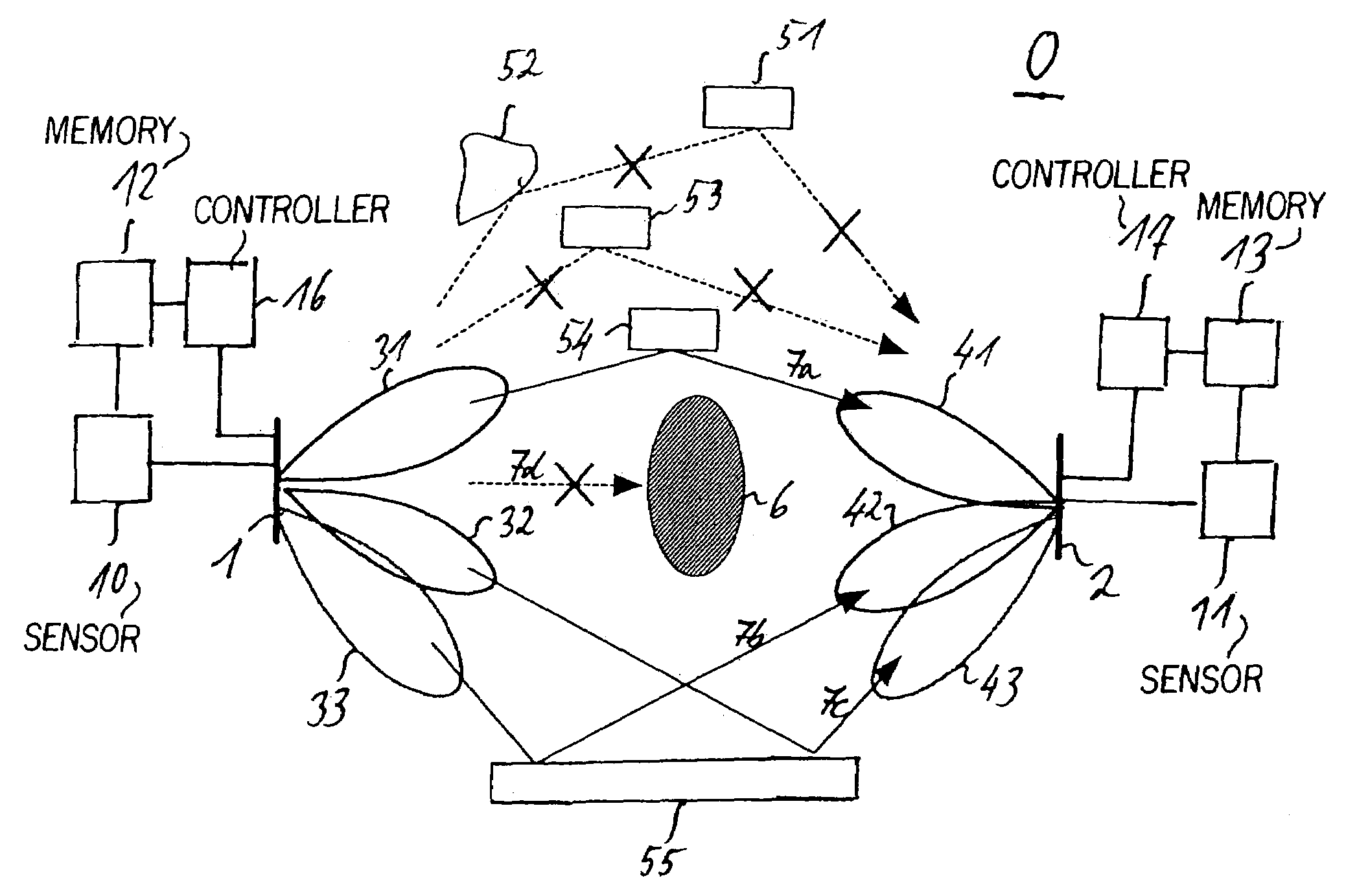
[0107]In the following, a preferred embodiment of the inventive communication system is explained by reference to FIG. 1.

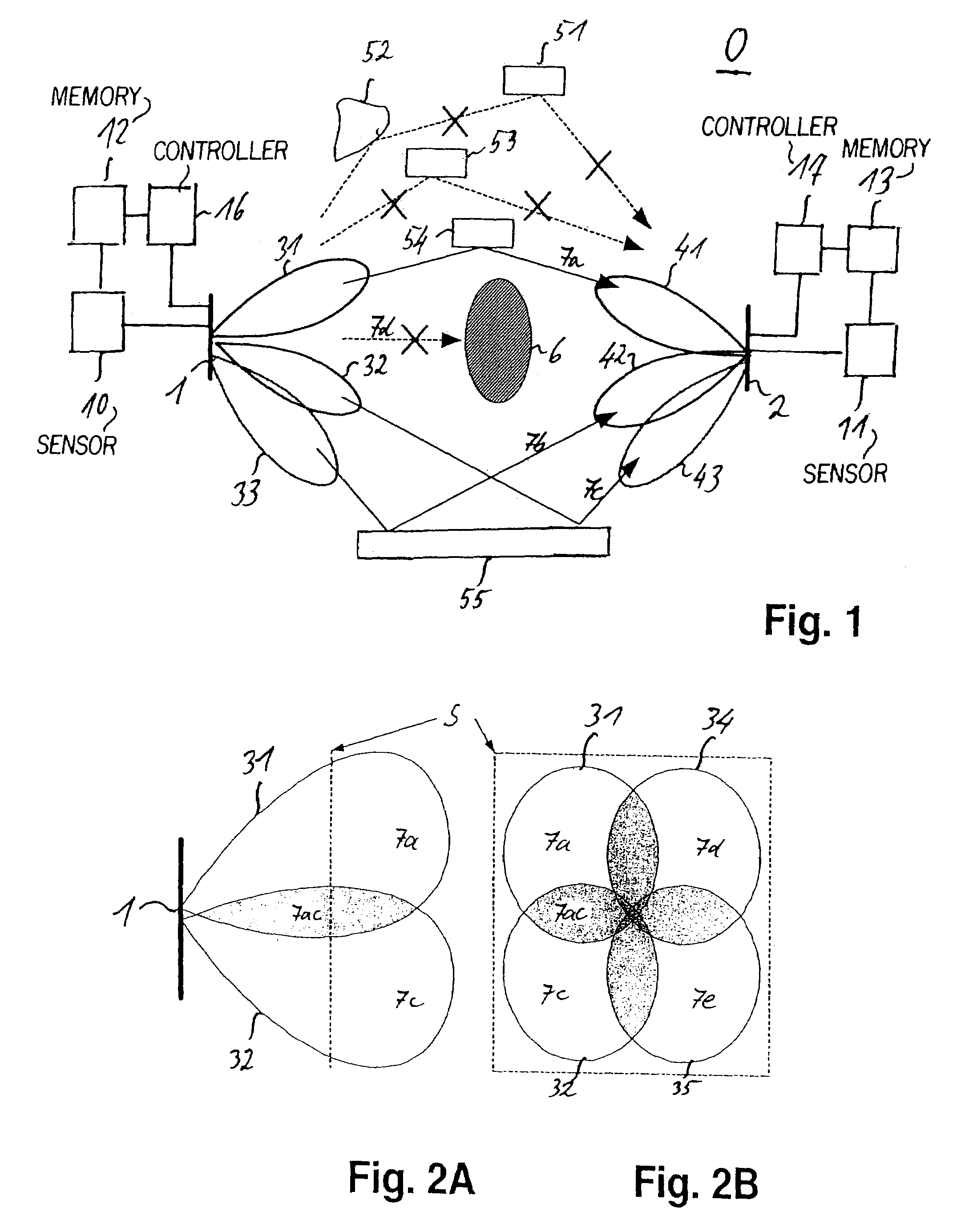
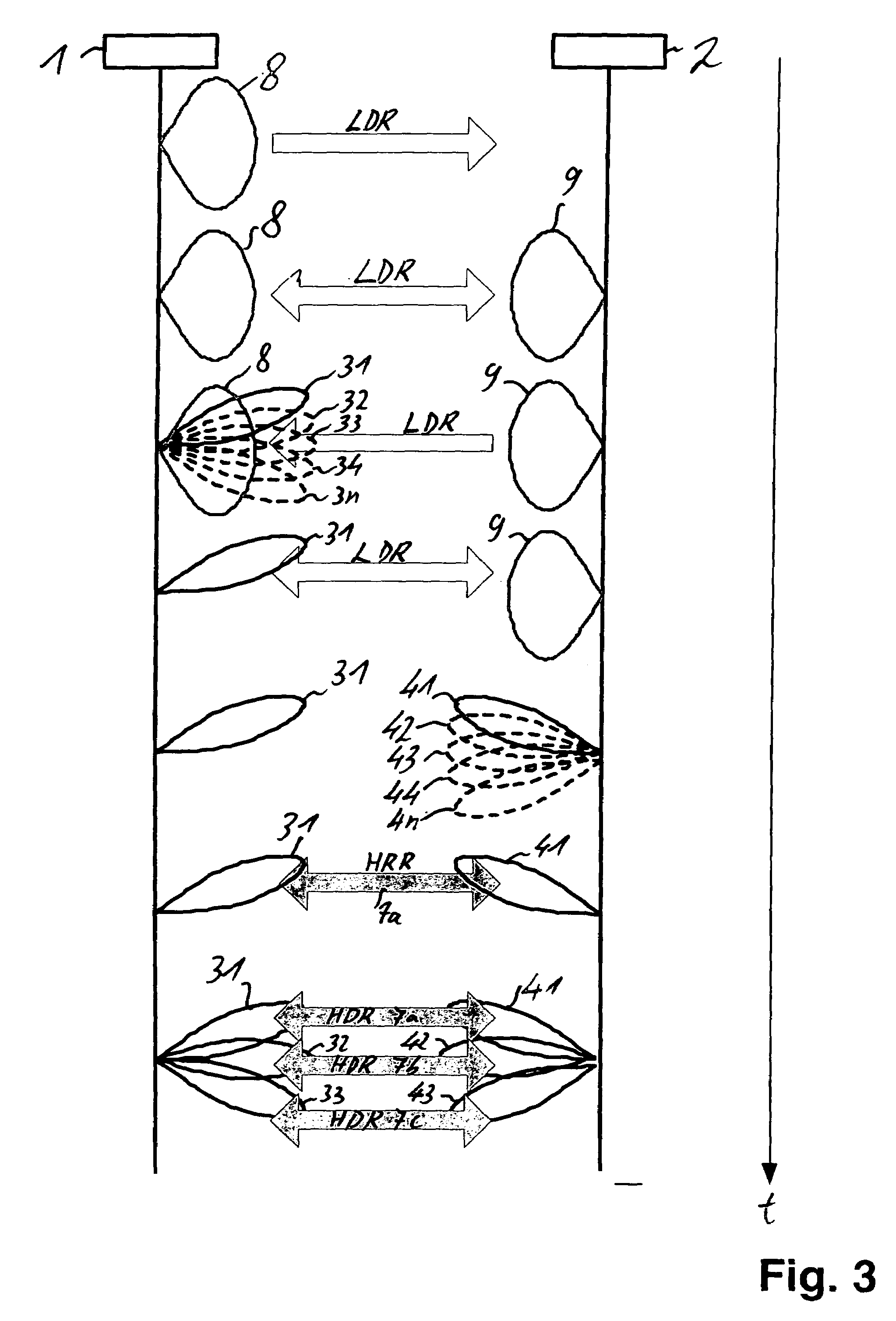
[0108]The communication system 0 comprises a first station 1 comprising three first narrow beam antennas 31, 32, 33 and a second station 2 comprising three second narrow beam antennas 41, 42, 43.

[0109]In the present embodiment, both the first and second narrow beam antennas 31, 32, 33, 41, 42, 43 are smart antennas.

[0110]The first and second stations 1, 2 are adapted to establish at least one first communication path 7a and one further communication path 7b, 7c for wireless communication via said first and second narrow beam antennas 31, 32, 33, 41, 42, 43 at the same time.

[0111]Said further communication path 7b, 7c is spatially different from said first communication path 7a.

[0112]Thus, according to the present invention, usage of several pairs of narrow (sharp) beam antennas 31, 32, 33, 41, 42, 43 for both a sending and receiving side of the station 1, 2 is pr...


PUM


Abstract

A communication system including a first station having at least two first narrow beam antennas and a second station having at least two second narrow beam antennas. The first and second stations establish a first communication path for wireless communication via a pair of first and second narrow beam antennas. When communication via the first communication path is disturbed by obstacles, the first and second stations automatically establish at least one alternative communication path, which is spatially different from the first communication path, for wireless communication using the at least two first narrow beam antennas and the at least two second narrow beam antennas.

Description

FIELD OF THE INVENTION[0001]The present invention relates to a communication system comprising the features of the preamble of independent claim 1. Furthermore, the present invention relates to a corresponding communication method.BACKGROUND OF THE INVENTION[0002]Wireless communication is used in a large variety of technical fields. Typical examples are mobile phone, wireless LAN, walkie-talkies, radio systems and point-to-point radio systems.[0003]The communication radius covered by a respective communication system basically depends on the technique used. Whereas GSM and UMTS are adapted for a communication radius up to about 10 km, wireless LAN frequently is restricted to about 100 m and the Bluetooth system usually is limited to about 20 m. The major influences on the communication range of a communication technique are the transmission frequency and output power used. Whereas only little absorption of electromagnetic waves in the atmosphere occurs at the transmission frequencie...

Claims


Application Information

Patent Timeline
IPC IPC(8): H04M1/00H04W16/28
CPCH04B7/0408H04B1/0483H04W16/28H04W24/04
Inventor UNO, MASAHIROWANG, ZHAOCHENGWULLICH, VOLKERHUANG, KAO-CHENG
Owner SONY DEUT GMBH
Why Eureka
Try Eureka