Distributed built-in test and performance monitoring system for electronic surveillance

a performance monitoring and built-in technology, applied in the direction of receiving monitoring, instruments, wireless communication, etc., can solve the problems of short test cycle, prone to operator error, and weak current test equipment and test system approach, so as to maintain accurate and repeatable performance of an esm system

Inactive Publication Date: 2010-03-23
ADVANCED TESTING TECH
View PDF5 Cites 40 Cited by
  • Summary
  • Abstract
  • Description
  • Claims
  • Application Information

AI Technical Summary

Benefits of technology

[0021]Using the test system and method in accordance with the invention, it now becomes possible to maintain accurate and repeatable performance o

Problems solved by technology

Manual testing of an ESM system has proven to be a long and cumbersome effort and prone to operator error.
Herein lies the weakness of the current test equipment and test systems approach.
Once deployed, the typical ESM system is subjected to harsh physical and environmental elements.
Even with the best of care, components within the

Method used


Image

  • Distributed built-in test and performance monitoring system for electronic surveillance
  • Distributed built-in test and performance monitoring system for electronic surveillance
  • Distributed built-in test and performance monitoring system for electronic surveillance

Examples


Embodiment Construction

[0032]Prior to detailing the operation of the invention, it should be understood that just about any ESM system can be designed to implement an embedded distributed test system in accordance with the teachings of the invention. To with, existing systems can be retrofitted using the approaches specified herein. ESM applications range from military submarine periscopes, military aircraft or military satellites to wherever an RF receiver is used for signal processing.

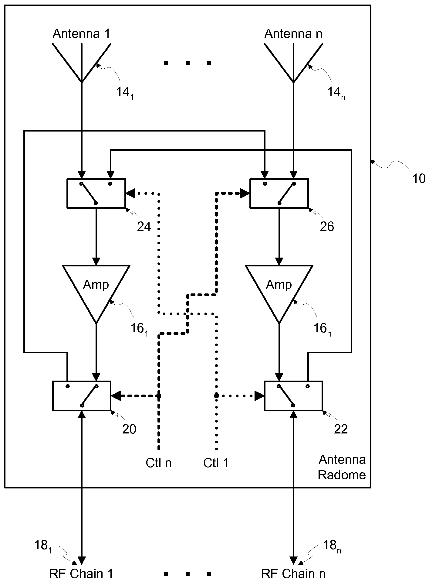
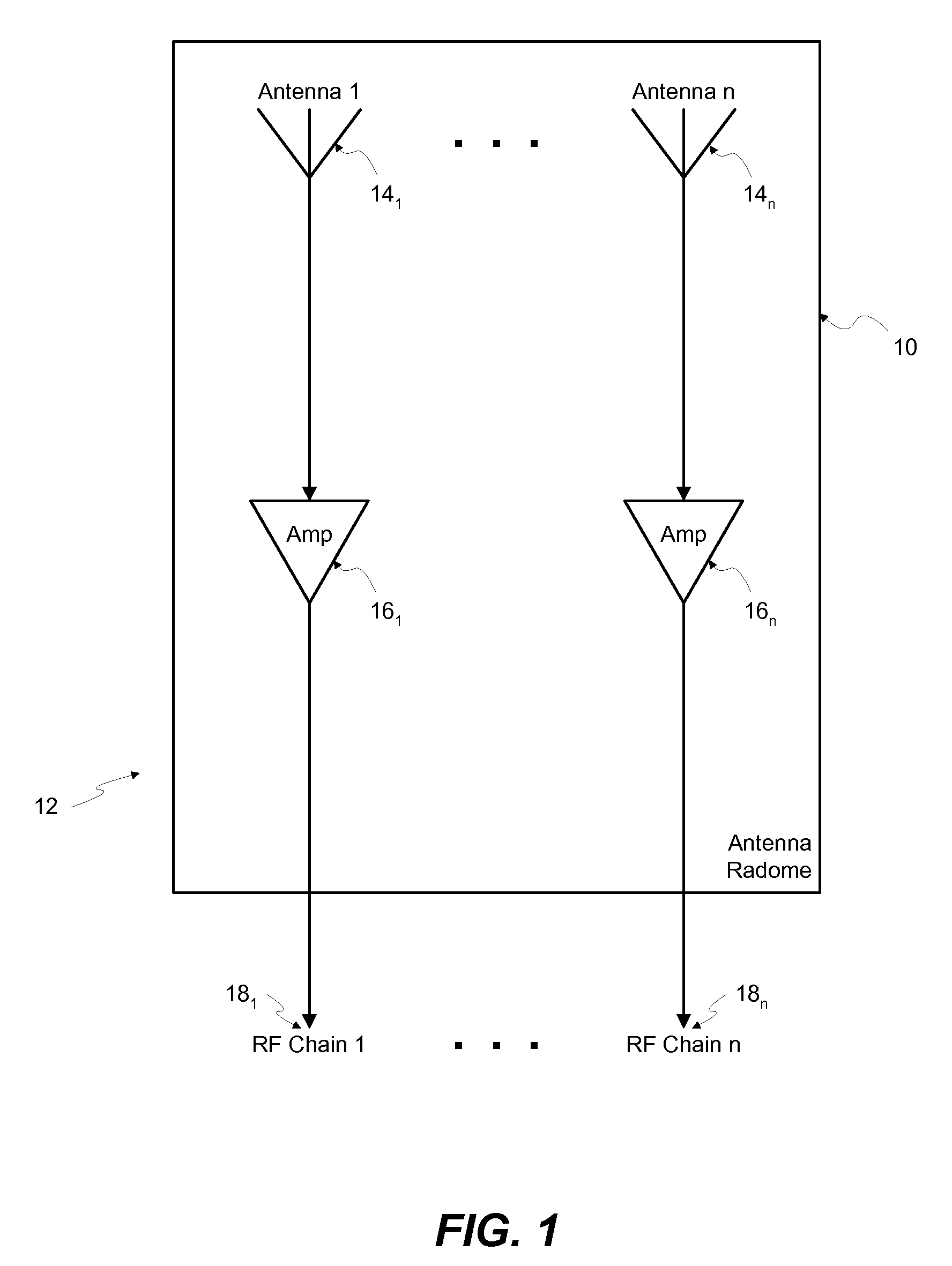
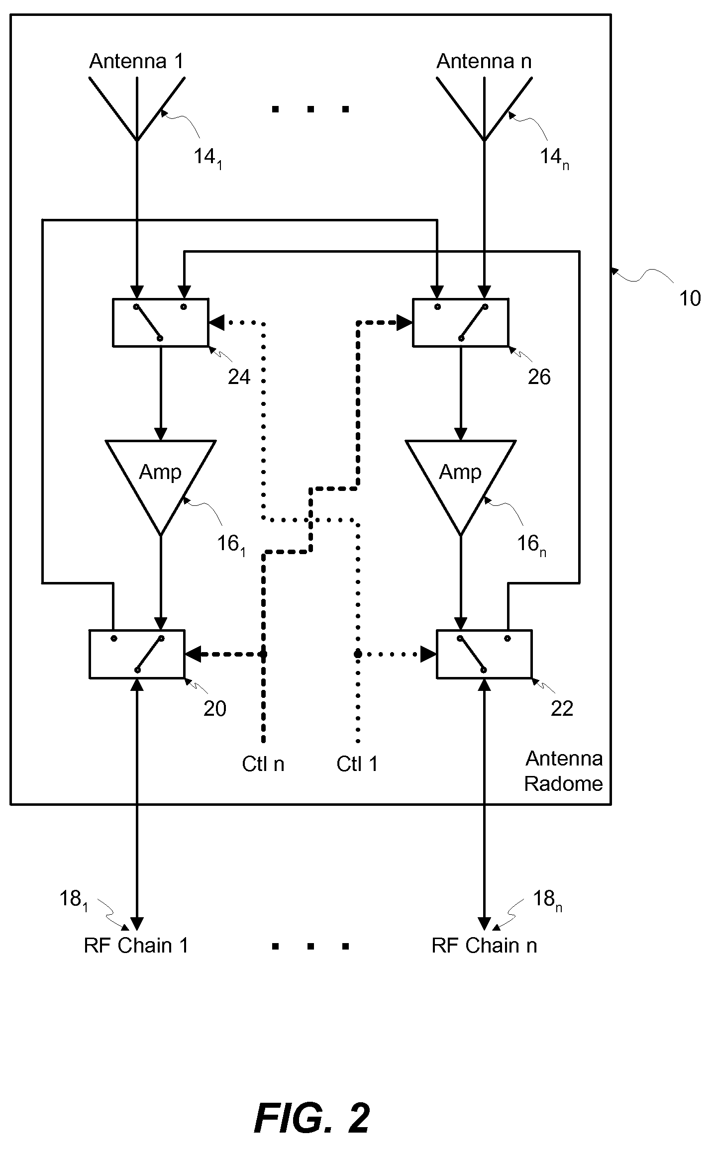
[0033]Referring to the drawings wherein like reference numerals refer to the same or similar elements, FIG. 1 shows an antenna radome 10 including a simplistic ESM RF chain 12 including at least one antenna 141, . . . , 14n (collectively designated as 14), a means of amplification 161, . . . , 16n (or amplifiers, collectively designated as 16) associated with each antenna 14 and an RF distribution chain 181, . . . , 18n (collectively designated as 18) associated with each amplifier 16. Most ESM systems implement a pluralit...


PUM


Abstract

A distributed test system for implementing enhanced BIT (Built-In-Test) within an ESM (Electronic Surveillance Monitoring) or RF receiver system. The distributed test system includes a system processor, a programmable RF source element or other comparable test signal generating arrangement, and switched path coupled elements and various measurement elements, each embedded at strategic locations within the ESM system so as to effect maximum path coverage and test benefit.

Description

CROSS REFERENCE TO RELATED APPLICATION[0001]This application claims priority under 35 U.S.C. §119(e) of U.S. provisional patent application Ser. No. 60 / 940,807 filed May 30, 2007, incorporated by reference herein.FIELD OF THE INVENTION[0002]The present invention relates generally to the field of automatic test systems for testing electronic radio frequency (RF) signals, and more particularly, to automatic test equipment for evaluating path response within an Electronic Surveillance Monitoring (ESM) system using a mix of frequency domain and time domain analyses.BACKGROUND OF THE INVENTION[0003]Automatic test equipment for testing the performance of RF communications systems, radar systems and other RF-related distribution components has been available for a number of years and is well established. A mix of scalar and vector network analyzers can be used to obtain a variety of S-parameter S11, S12, S21, S22 measurements in addition to phase and delay measurements on RF components.[00...

Claims


Application Information

Patent Timeline
IPC IPC(8): G01R29/10
CPCH04K3/822H04B17/20H04K3/94H04B7/08H04K2203/32H04W24/06
Inventor ENGEL, RICHARDKORPI, EMERY
Owner ADVANCED TESTING TECH
Why Eureka
Try Eureka