Fiber optic temperature and pressure sensor and system incorporating same

a technology of temperature and pressure sensors and fiber optic fibers, applied in the field of fiber optic sensors, can solve the problems of large dynamic range, unsuitable for measuring temperature, large bandwidth, etc., and achieve the effect of simple and effective compensation for temperature-pressure cross-sensitivity

Inactive Publication Date: 2010-03-23
SCHLUMBERGER TECH CORP
View PDF20 Cites 12 Cited by
  • Summary
  • Abstract
  • Description
  • Claims
  • Application Information

AI Technical Summary

Benefits of technology

[0013]It is therefore an object of the invention to provide a fiber optic sensor (and sensing systems based thereon) that allows for simple and effective compensation for temperature-pressure cross-sensitivity.
[0016]It is also an object of the invention to provide such a fiber optic sensor which is rugged and inexpensive.
[0018]It will be appreciated that the components of the sensing system simply and effectively compensate for temperature-pressure cross-sensitivity of the sensor(s). It also provides a sensor that is rugged and inexpensive.

Problems solved by technology

In addition, fiber optic sensors have the potential for very high sensitivity, large dynamic range, and wide bandwidth.
Moreover, the relative insensitivity of the side hole fiber optic pressure sensor to temperature makes it unsuitable for measuring temperature.
Similar to the side hole fiber optic pressure sensor, temperature affects the birefringence of the core and it is difficult to separate the pressure-related and the temperature-related contributions to the overall wavelength shift in the reflected spectral envelope.
Thus, in certain applications where both temperature and pressure are variable, complex measures must be taken to compensate for the effects of temperature on the birefringence.
However, such compensation schemes are difficult and costly to implement for different applications and installations.
Additionally, the wavelength sensitivity to pressure in this approach is quite small (about 1 picometer / 18 psi (1 picometer / 1.27 kg per square cm)), and it is difficult to achieve better than 0.1 picometer (pm) wavelength resolution with current optical technology.
Therefore, it is very difficult to use this approach in most applications in which a high resolution pressure measurement is required.
A mechanical amplifier can be applied to the fiber grating in order to increase its pressure sensitivity, but this makes it more difficult to manufacture and creates stability and repeatability problems.

Method used


Image

  • Fiber optic temperature and pressure sensor and system incorporating same
  • Fiber optic temperature and pressure sensor and system incorporating same
  • Fiber optic temperature and pressure sensor and system incorporating same

Examples


Embodiment Construction

[0026]As used herein, the term “upstream” is generally defined as disposed closer to the light source of the system. Conversely, “downstream” generally means disposed further away from the light source of the system.

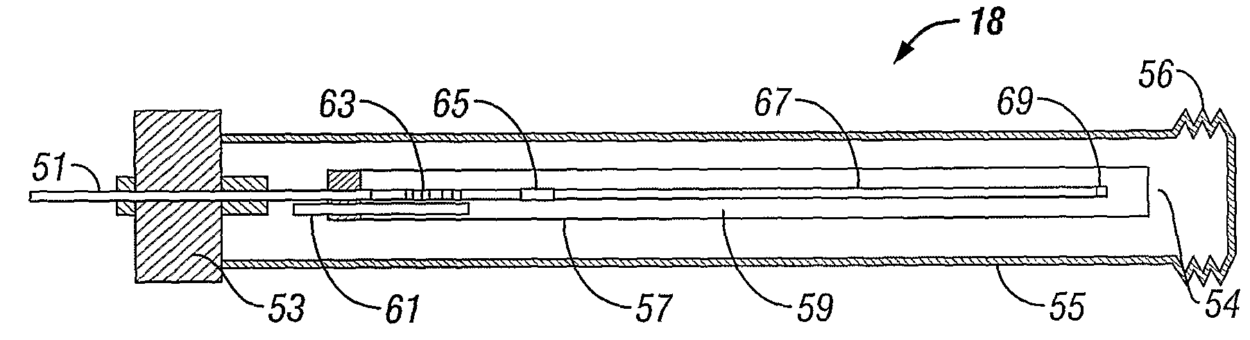
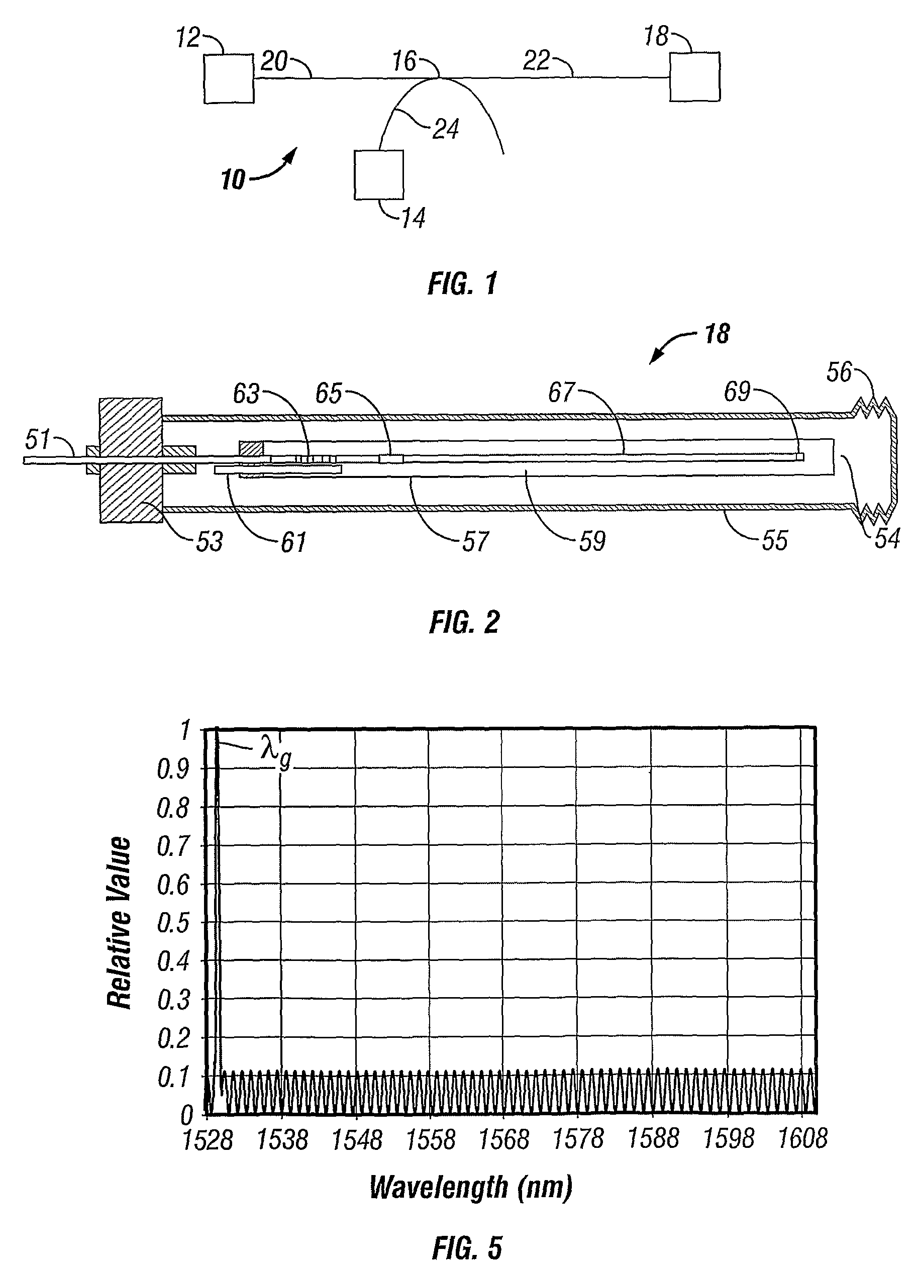
[0027]Turning now to FIG. 1, an exemplary fiber optic sensing system 10 according to the invention generally includes a light source 12, a beam splitter 16, a spectral analyzer 14 and one or more fiber optic sensors 18. A waveguide 20 (such as a fiber optic waveguide directs the light generated by the light source 12 to the beam splitter 16. The beam splitter 16 directs this light to the fiber optic sensor(s) 18 over fiber optic waveguide 22, where spectral components of such incident light are reflected back along the waveguide 22. The beam splitter 16 directs the desired components of the returning light to the spectral analyzer 14, preferably via a fiber optic waveguide 24. The light source 12 provides different wavelength components and may be realized by a tunable l...


PUM

PropertyMeasurementUnit
reflectivityaaaaaaaaaa
angleaaaaaaaaaa
diameteraaaaaaaaaa

Abstract

A sensing system including a sensor having an enclosure that defines a chamber, a fiber optic segment extending from outside the enclosure into the chamber, and a sequence of optical processing elements within the chamber. The elements include a fiber Bragg grating, a polarizer, a side hole fiber, and a mirror. A light source is arranged to direct light to the sensor(s). A spectral analyzer is arranged to detect light reflected back from the sensor(s). The fiber Bragg grating substantially reflects a first spectral envelope while transmitting the remainder of the optical spectrum to the polarizer and side hole fiber. The polarizer, side hole fiber, and mirror cooperate to return an optical signal within a second spectra! envelope. The characteristic wavelength of a peak in the first spectral envelope is highly sensitive to temperature and relatively weakly sensitive to pressure. The period of the optical signal within the second spectral envelope is highly sensitive to pressure and relatively weakly sensitive to temperature. The spectral analyzer measures these spectral components to simultaneously derive a measure of temperature and pressure that effectively compensates for temperature-pressure cross-sensitivity of the sensor(s).

Description

BACKGROUND OF THE INVENTION[0001]1. Field of the Invention[0002]This invention relates to fiber optic sensors for measuring temperature and pressure and to systems based thereon.[0003]2. Description of Related Art[0004]Optical fibers generally include a cylindrical core, a concentric cylindrical cladding surrounding the core, and a concentric cylindrical protective jacket surrounding the cladding. The core is made of transparent glass or plastic having a certain index of refraction. The cladding is also made of transparent glass or plastic, but having a different, smaller, index of refraction. The ability of the optical fiber to act as a bendable waveguide is largely determined by the relative refractive indices of the core and the cladding.[0005]The refractive index of a transparent medium is the ratio of the velocity of light in a vacuum to the velocity of light in the medium. As a beam of light enters a medium, the change in velocity causes the beam to change direction. More spec...

Claims


Application Information

Patent Timeline
Patent Type & Authority Patents(United States)
IPC IPC(8): G02B6/00G02B6/26G01D5/353G01K11/32G01L9/00G01L11/02G01L19/00G02B6/02G02B6/34
CPCG01D5/35303G01K11/3206G01L9/0039G01L11/025G01L19/0092G02B6/0218G02B6/022G02B6/276G02B6/29317G01D5/35316G01D5/35354
Inventor CHEN, YUEHUA
Owner SCHLUMBERGER TECH CORP
Why Eureka
Try Eureka