Distortion compensation in wireless digital communication

a technology of distortion compensation and wireless digital communication, applied in the direction of digital transmission, modulation, baseband system details, etc., can solve the problems of affecting the quality of transmission signals, and increasing the scale of devices and manufacturing costs

Inactive Publication Date: 2010-03-30
FUJITSU LTD
View PDF11 Cites 4 Cited by
  • Summary
  • Abstract
  • Description
  • Claims
  • Application Information

AI Technical Summary

Benefits of technology

[0013]The present invention is conceived in view of the above-described problems in the prior art, and it is an object of the invention to provide a distortion compensation technique that allows a transmitter to transmit a high-quality distortion-compensated and quadrature modulated signal, without causing undesirable leakage of out-of-band radiation.

Problems solved by technology

However, since sophisticated and high-performance devices and circuits are required in broadband radio transmission, the device scale and the manufacturing cost increase consequently.
However, with such a direct RF modulation scheme, errors are generated in both the in-phase component and the quadrature component of the transmission signal to be supplied to the quadrature modulator, due to variation in analog devices and change over time.
As a result, undesirable leakage of waves is generated as imaginary components in the modulated analog transmission signals, which causes degradation of the transmission signal quality.
Even if the delay time is correctly set in the delay element, the phase of the feedback signal itself fluctuates due to clock jitter caused by thermal noise or external disturbance.
In short, it is difficult for a conventional adaptive predistortion technique to guarantee stable and reliable distortion compensation, which technique is likely to generate undesirable out-of-band power radiation.
However, due to malfunction of analog circuits, including an oscillator for a down converter, the phase difference between the reference signal and the feedback signal may not be correctly determined.
In this case, distortion compensation and / or other corrections cannot be performed correctly, causing abnormal operations.

Method used


Image

  • Distortion compensation in wireless digital communication
  • Distortion compensation in wireless digital communication
  • Distortion compensation in wireless digital communication

Examples


Embodiment Construction

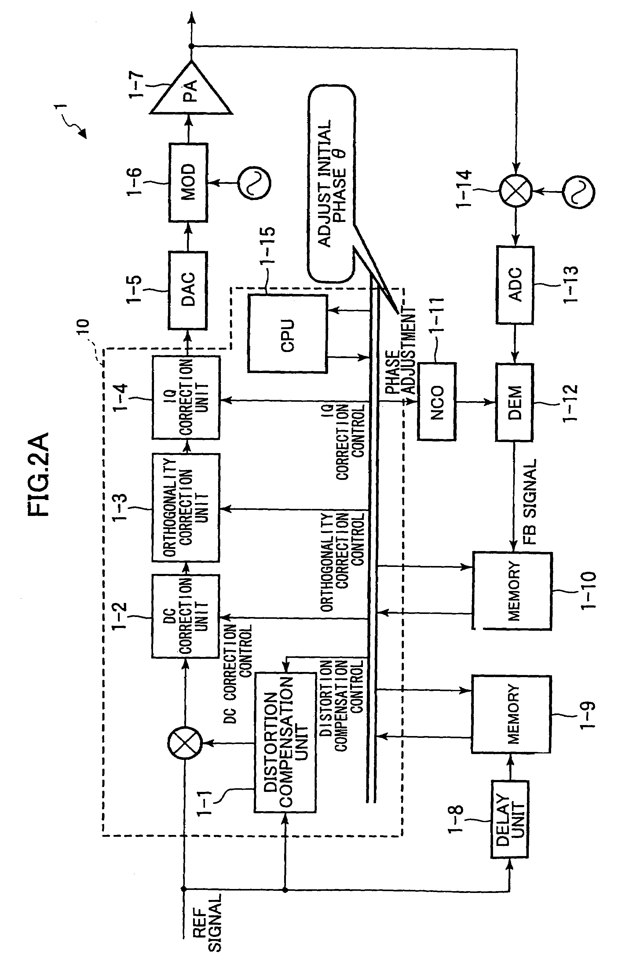
[0029]FIG. 2A is a schematic block diagram of a distortion compensating device 10 applied to a transmitter 1 of a direct RF modulation type, and FIG. 2B is a schematic block diagram of CPU 1-15 shown in FIG. 2A. The transmitter 1 (or the distortion compensating device 10) includes a distortion compensation unit 1-1, a direct current (DC) correction unit 1-2, an orthogonality correction unit 1-3, an IQ correction unit 1-4, a digital-to-analog converter (DAC) 1-5, and a CPU 1-15. The transmitter 1 also includes a quadrature modulator (MOD) 1-6, a power amplifier (PA) 1-7, a delay unit 1-8, memories 1-9 and 1-10, a digital oscillator (NCO) 1-11, a quadrature demodulator (DEM) 1-12, an analog-to-digital converter (ADC) 1-13, and a down converter 1-14.

[0030]The CPU 1-15 includes a phase adjusting unit 21, a phase adjustment result storing unit 22, a phase adjustment result comparison and determination unit 23, and a correction control unit 24, as illustrated in FIG. 2B. The correction co...


PUM


Abstract

A distortion compensating technique applied to a transmitter for transmitting a quadrature modulated signal in a wireless digital communication system is provided. A phase adjustment value is determined for a quadrature demodulated feedback signal based on comparison between the feedback signal and a reference signal to be transmitted from the transmitter. This phase adjustment value is compared with the previous phase adjustment value. If the comparison result between the current and previous phase adjustment values satisfies a prescribed condition, correction for quadrature modulation, such as DC offset correction, orthogonality correction, or IQ amplitude correction, is performed.

Description

BACKGROUND OF THE INVENTION[0001]1. Field of the Invention[0002]The present invention generally relates to distortion compensation, and more particularly, to a distortion compensation technique applied to a transmitter for transmitting quadrature modulated signals in wireless digital communication systems.[0003]2. Description of the Related Art[0004]In mobile communications, including IMT-2000, broadband radio services are being offered, and especially, broader-band radio transmission is being discussed for the next-generation mobile communication schemes. In general, complex baseband signals are first converted to an intermediate frequency (IF) band, and the IF signals are further converted to radio frequency (RF) signals suitable for broadband radio transmission.[0005]Such broadband mobile communication systems require bandpass filters to have steep filter characteristics, as well as a flat characteristic over the entire passband, in order to sufficiently reduce high-frequency com...

Claims


Application Information

Patent Timeline
Patent Type & Authority Patents(United States)
IPC IPC(8): H04L25/49H03C1/06
CPCH03F1/3247H04L27/364H04L27/368H04L2027/0016
Inventor OHBA, TAKESHIFUNYU, YASUHITOSHAKO, HIDEHARU
Owner FUJITSU LTD
Why Eureka
Try Eureka