
Method and means for producing a magnetically induced design in a coating containing magnetic particles

a technology of magnetic particles and coatings, applied in the field of security document printing, can solve the problems of inability to combine optically variable and magnetic properties in the same pigment, the cost of optically variable pigments is more expensive in manufacturing, and the composition of optically variable pigments is not feasibl

Active Publication Date: 2010-04-06
SICPA HLDG SA
View PDF32 Cites 19 Cited by
  • Summary
  • Abstract
  • Description
  • Claims
  • Application Information

AI Technical Summary

Benefits of technology

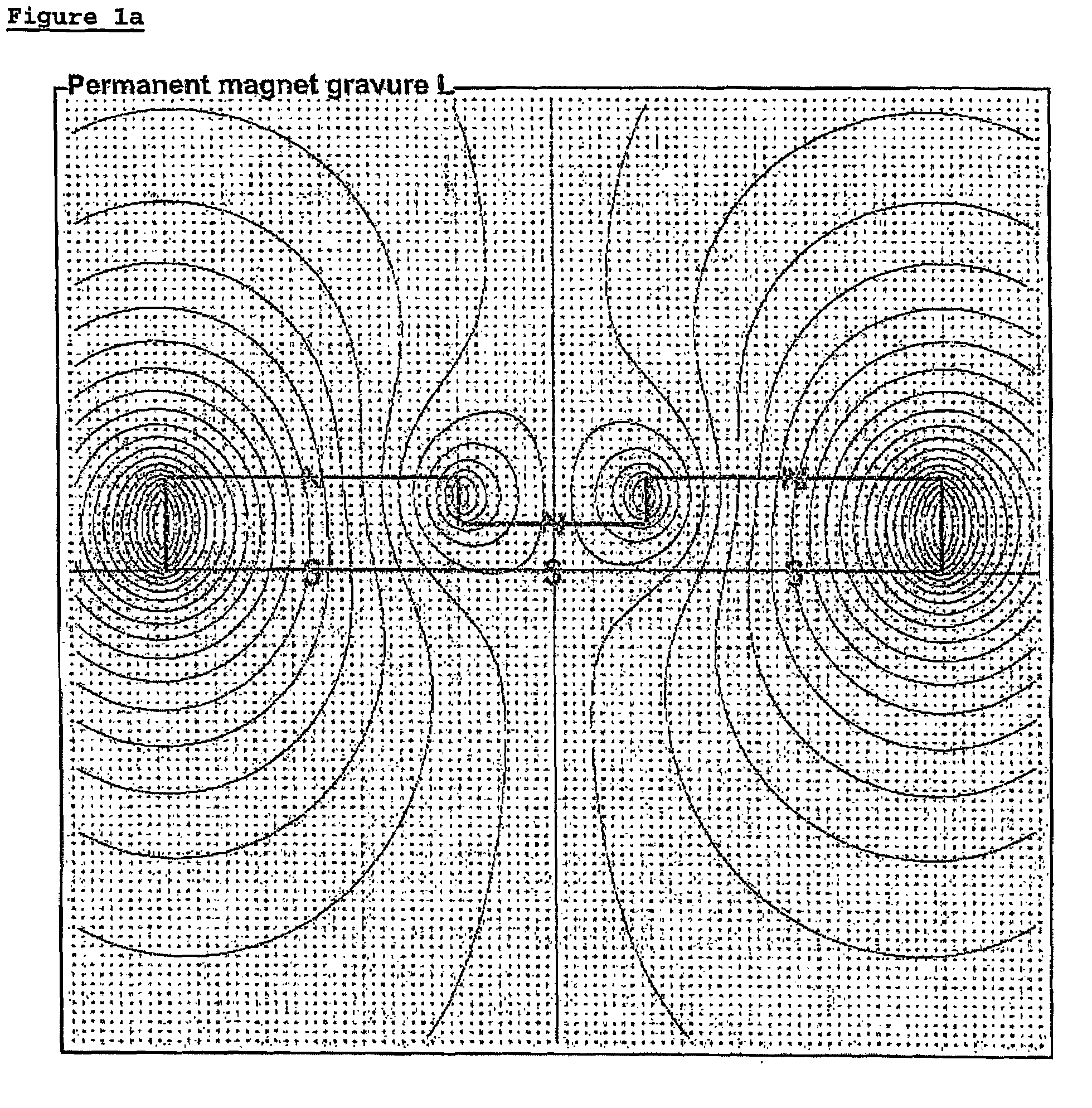
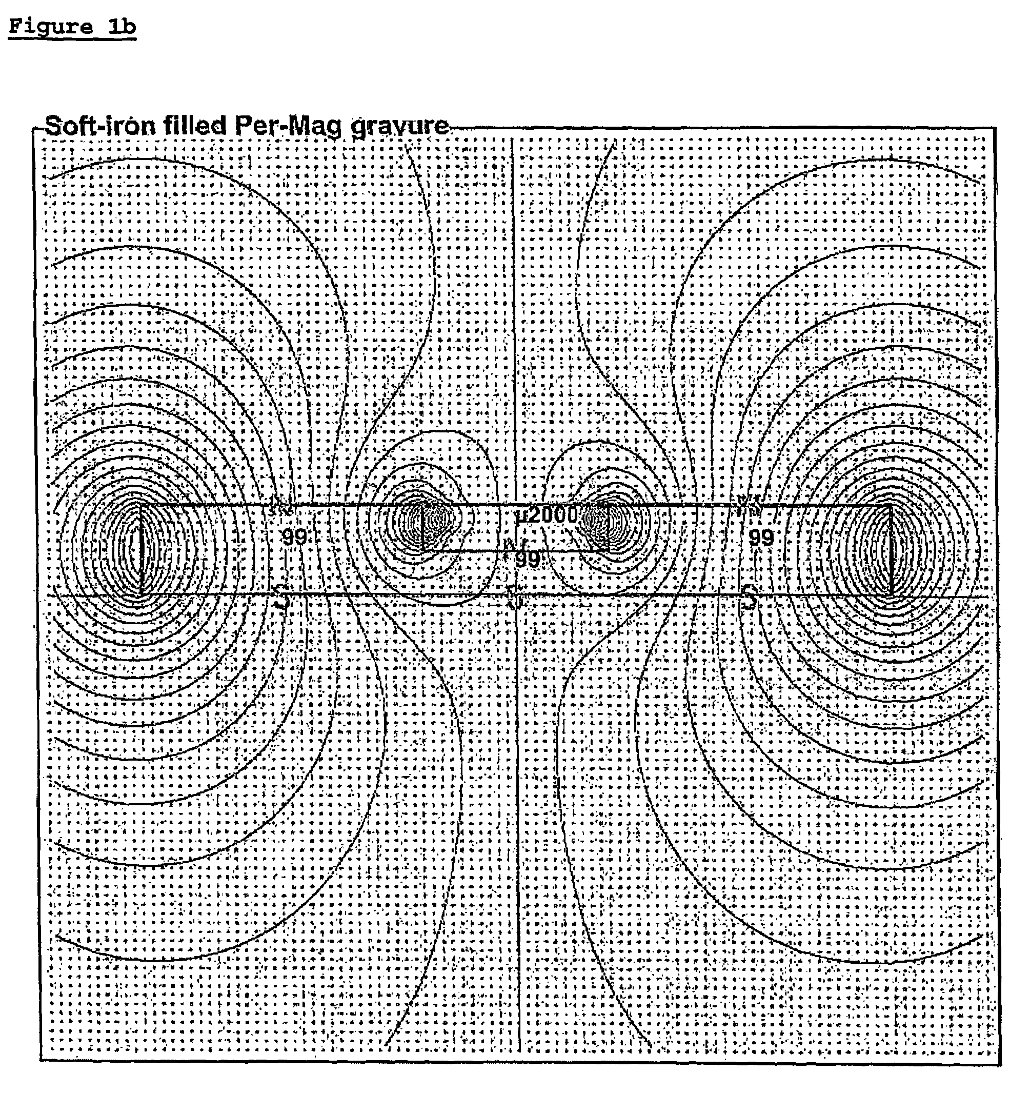
The present invention is about a new way to apply magnetic fields to ink or coatings during printing to create high-resolution magnetic designs on printed articles. The invention involves using a device with a magnetized surface to transfer the magnetic design onto a wet coating on a substrate. The device has irregularities on its surface that create a magnetic field that can transfer the design onto the substrate. The invention solves the technical problem of creating a customer-specific high-resolution magnetic design on a printed article in an easy-implemented and reliable way. The invention can be used with any mechanically workable permanent-magnetic material and can be applied to a range of substrates such as paper or plastic. The invention also provides a pre-formed body of magnetic material that can be applied to a substrate to create a magnetic design.

Problems solved by technology

The technical problem to be solved in this context is to find a next-generation upgrade for optically variable ink on bank notes and security printing products.
The optically variable pigments and coating compositions which are sold for decorative applications are not suited for magnetic orientation;ii) The combination of optically variable and magnetic properties in a same pigment is not feasible without having access to the manufacturing of the optically variable pigment;iii) The magnetic optically variable pigment is more expensive in manufacturing than ordinary optically variable pigment, and the imparting of the magnetic design requires the printing machine to be equipped with supplementary technology for magnetic orientation.
The optical effect of the magnetic design is furthermore far less appealing to the decorative market than the optically variable effect itself.
It is thus not expected that magnetic optically variable inks will ever have any substantial market potential outside the very field of security printing.
None of these methods has proved suited, however, for the transfer of a high-resolution magnetic pattern in a high-speed printing process.

Method used


Image

  • Method and means for producing a magnetically induced design in a coating containing magnetic particles
  • Method and means for producing a magnetically induced design in a coating containing magnetic particles
  • Method and means for producing a magnetically induced design in a coating containing magnetic particles

Examples


example 1

[0069]A Plastoferrite plate, magnetised in a direction perpendicular to the surface (model M100.8, Maurer magnetics AG, CH-8627 Grüningen), was engraved on a computer-controlled mechanical engraving station with text of different sizes (see FIG. 2a). The characteristics of these engraving were as follows:[0070]Text height and width: form 3 to 7 mm[0071]Depth of engraving: 150 μm for the smallest characters, up to 250 μm for the largest[0072]Line width: from 200 μm for the smallest characters to 800 μm for the largest

[0073]An OVI® silkscreen ink of the following formula, comprising a magnetic optically variable pigment, was prepared:

[0074]

Diethyl ketone23%Ethyl diglycol29%Solution Vinyl VMCA (Union Carbide)22%BYK-053 (BYK) 1%Magnetic Optically Variable Pigment*25%*magenta-to-green, 7 layers design as disclosed in WO 02 / 73250: Cr / MgF2 / Al / Fe—Ni / Al / MgF2Cr. The Fe—Ni alloy was 85% Fe / 15% Ni.

[0075]The vinyl resin was dissolved in the ketone-glycol solvent prior to the incorporation of the...

example 2

[0078]A Plastoferrite plate (model M201.1, Maurer magnetics AG, CH-8627 Grüningen) was magnetised in a direction perpendicular to the surface and then engraved on a computer-controlled mechanical engraving station with a geometrical design (two pyramids; see FIG. 3a). The characteristics of the engraving were as follows:

[0079]

Height and width:1.5 × 2.4cmDepth of engraving:200μmLine width:200μm

[0080]The engraving corresponding to the upper pyramid was filled up with a polymer, so as to result in an even surface of the engraved plate; the engraving corresponding to the lower pyramid was left as such.

[0081]An OVI® flexography ink comprising a magnetic optically variable pigment of the following formula was prepared:

[0082]

Neocryl BT-105 (Avecia)41.5% Deionised water 18%Dowanol DPM (Dow)  6%AMP-95 ™ (Angus Chemie GmbH)1.5%Neocryl BT-100  7%Tego Foamex 800 (Tego Chemie Service GmbH)0.5%Aerosil 200 (Degussa)0.5%Magnetic Optically Variable Pigment* 25%*green-to-blue, 5 layers design, Cr / MgF...

example 3

[0086]A Plasto-ferrite plate as used in example 1 was engraved on a computer-controlled mechanical engraving station with text (see FIG. 4a). The characteristics of the engraving were as follows:

[0087]

Text height and width:7mmDepth of engraving:250μmLine width:300μm

[0088]An UV drying soft-magnetic screen ink without optically variable properties was prepared according to the following formula and known procedures:

[0089]

Epoxyacrylate oligomer37.5%  Trimethylolpropane triacrylate monomer14% Tripropyleneglycol diacrylate monomer14% Genorad 16 (Rahn)1%Fine iron powder25% Aerosil 200 (Degussa-Heuls)1%Irgacure 500 (CIBA)6%Genocure EPD (Rahn)2%

[0090]A patch of the ink was screen-printed on a white PVC support (100 g / m2) and the imprinted support was processed as described in example 1, except that the ink was dried in situ using an UV-radiation curing unit.

[0091]FIG. 4b shows that again, the design engraved in the plate has been transferred to the soft-magnetic ink patch; the latter shows ...


PUM

PropertyMeasurementUnit
thicknessaaaaaaaaaa
widthaaaaaaaaaa
Depthaaaaaaaaaa

Abstract

The invention discloses a device and a method for transferring a predeterminable, high-resolution magnetic design onto a document printed with a magnetic ink, in particular a magnetic optically variable ink. The device comprises a body of a composite permanent-magnetic material, having at least one flat or curved surface engraved with indicia corresponding to the design to be transferred, wherein the said magnetic material is permanently magnetized, preferably in a direction substantially perpendicular to the said surface. The method comprises imprinting or coating a first surface of a sheet or web with a magnetic ink or coating composition, and approaching the imprinted sheet or web to the engraved surface of a body of magnetized composite permanent-magnetic material while the ink is wet, followed by hardening the ink.

Description

FIELD OF INVENTION[0001]The invention is in the field of security document printing. It concerns a novel means for transferring a security design into magnetic ink, in particular magnetic color-shifting ink, and a method to realize said design.STATE OF THE ART[0002]Markings exhibiting a viewing-angle dependent light reflection spectrum (“optically variable devices”, OVDs) are used as an efficient anti-copy means on bank notes and security documents. Among the OVDs, optically variable inks (OVI®; EP 227,423 B1) have acquired a preeminent position since their first introduction on currency back in 1987. Such inks are formulated on the basis of optically variable pigment (OVP), a preferred type of OVP being the flaky thin-film optical interference device described in U.S. Pat. No. 4,705,300; U.S. Pat. No. 4,705,356; U.S. Pat. No. 4,721,217; U.S. Pat. No. 4,779,898; U.S. Pat. No. 4,930,866; U.S. Pat. No. 5,084,351 and in related disclosures. Other useful types of OVP comprise the multip...

Claims


Application Information

Patent Timeline
Patent Type & Authority Patents(United States)
IPC IPC(8): B32B5/16B42D15/10G03G19/00H01F1/01B05D3/14B05D5/06B41C1/02B41C1/04B41C1/05B41M1/10B41M1/42B41M3/14B41N1/06
CPCB05D3/207B41M1/10B41M1/42B41N1/06B42D25/41B42D25/425B42D25/29B05D5/061Y10T428/24909B41C1/02B41C1/025B41C1/05B42D2033/16B42D2033/20B42D2035/20Y10S428/90Y10S428/916Y10T428/24893Y10T428/256B41M3/14B41C1/04B42D25/369B42D25/378B32B5/16
Inventor BENNINGER, NATHALIEDESPLAND, CLAUDE-ALAINDEGOTT, PIERREMULLER, EDGAR
Owner SICPA HLDG SA
Learn More