Scintillator crystal and radiation detector

a scintillator and radiation detector technology, applied in the direction of instruments, x/gamma/cosmic radiation measurement, crystal growth process, etc., can solve the problem of rendering the scintillator unsuitable for a photomultiplier tube, and achieve the effect of high transparency and greater fluorescen

Inactive Publication Date: 2010-04-06
OXIDE
View PDF13 Cites 11 Cited by
  • Summary
  • Abstract
  • Description
  • Claims
  • Application Information

AI Technical Summary

Benefits of technology

[0050]The proportion of M in the scintillator crystal represented by general formula (1) is preferably 0.0001-0.05% by weight, more preferably 0.0001-0.01% by weight and even more preferably 0.0005-0.01% by weight based on the total weight of the scintillator crystal. If the proportion is less than 0.0001% by weight, it will tend to be difficult to achieve the effect of the invention. If the proportion exceeds 0.05% by weight, more cracks will tend to be produced in the scintillator crystal.
[0051]The scintillator crystal of this embodiment exhibits two maximum values in the fluorescence intensity distribution for the wavelength of emitted fluorescence, and of these maximum values, the fluorescence intensity for the maximum value at the short wavelength end divided by the fluorescence intensity for the maximum value at the long wavelength end (fluorescence intensity ratio) is preferably greater than 0.7, and more preferably 0.8 or greater. A fluorescence intensity ratio of 0.7 or smaller may not allow improvement in the light output described hereunder. On the other hand, a fluorescence intensity ratio of 0.8 or greater can result in even greater fluorescence at a wavelength compatible with the sensitivity wavelength peak of the photomultiplier tube.
[0052]The fluorescence intensity distribution can be obtained by adding a dopant, in an amount that will not produce cracking in the scintillator crystal, in order to affect the electronic state of the Ce3+ and alter the electron transition.
[0053]The scintillator crystal of this embodiment is preferably a single crystal from the standpoint of obtaining a scintillator with high transparency.
[0054]The method of producing the scintillator single crystal may be, for example, the Bridgman method or Czochralski method whereby a mixture of a halogenated compound and dopant is heated to melting and then cooled for crystallization.
[0055]A process for production of a scintillator single crystal according to an embodiment of the invention by the Bridgman method will now be explained.

Problems solved by technology

As a result, the signal actually obtained through the photomultiplier tube is small for the magnitude of the fluorescent light quantity of the scintillator, rendering the scintillator unsuitable for a photomultiplier tube.

Method used


Image

  • Scintillator crystal and radiation detector
  • Scintillator crystal and radiation detector
  • Scintillator crystal and radiation detector

Examples


example 1

[0071]The starting matrix material for the scintillator crystal comprised 25 g of LaBr3 (99.99% purity, product of Aldrich Co.) and 0.125 g of CeBr3 (99.99% purity, product of Aldrich Co.). The dopant starting material for the scintillator crystal comprised 2.5125 mg of NaBr (99.99% purity, product of Aldrich Co.), 2.5125 mg of FeBr2 (99.99% purity, product of Aldrich Co.) and 2.5125 mg of NiBr2 (99.99% purity, product of Aldrich Co.). The matrix starting material and dopant starting material were combined to obtain a mixture.

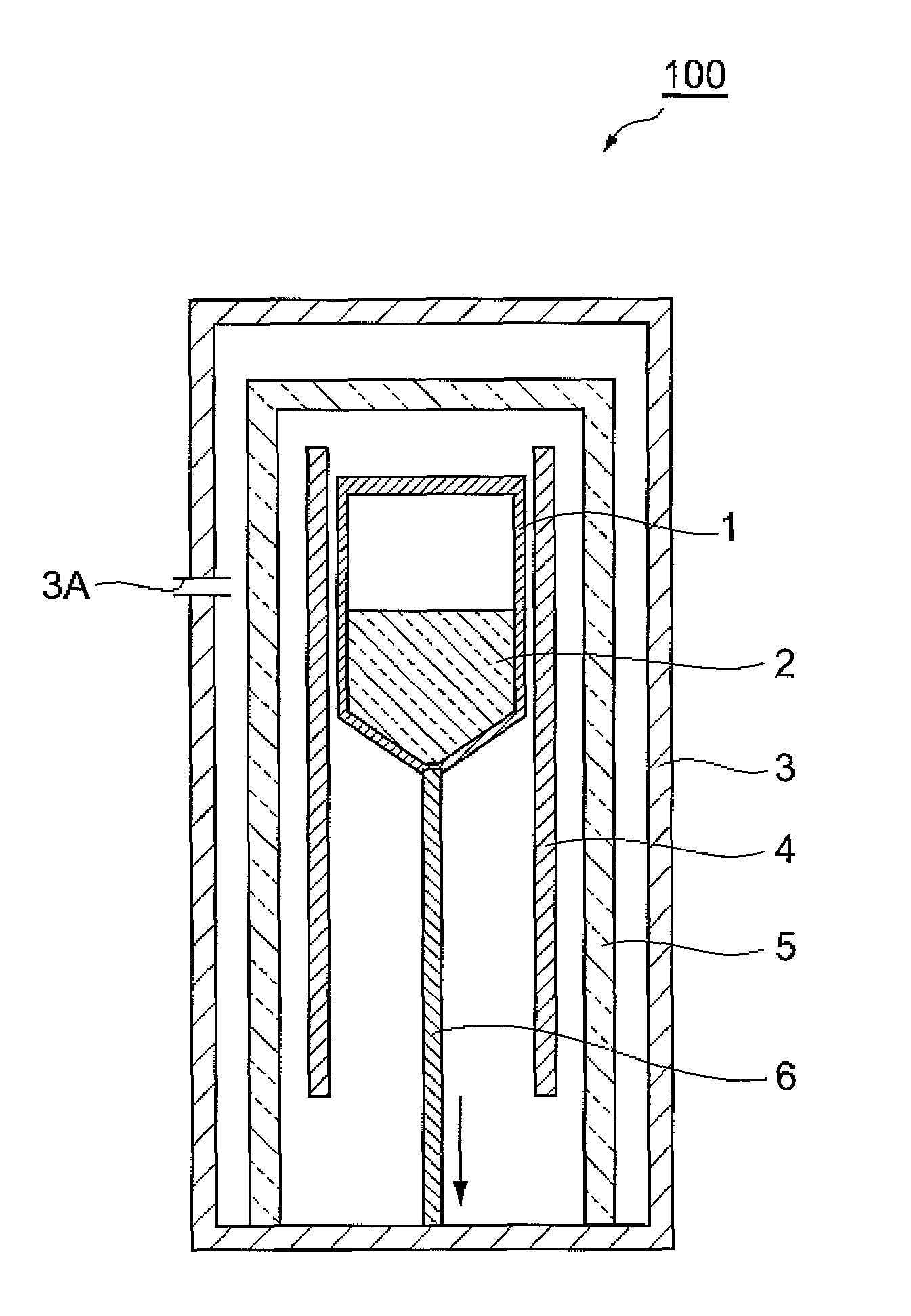
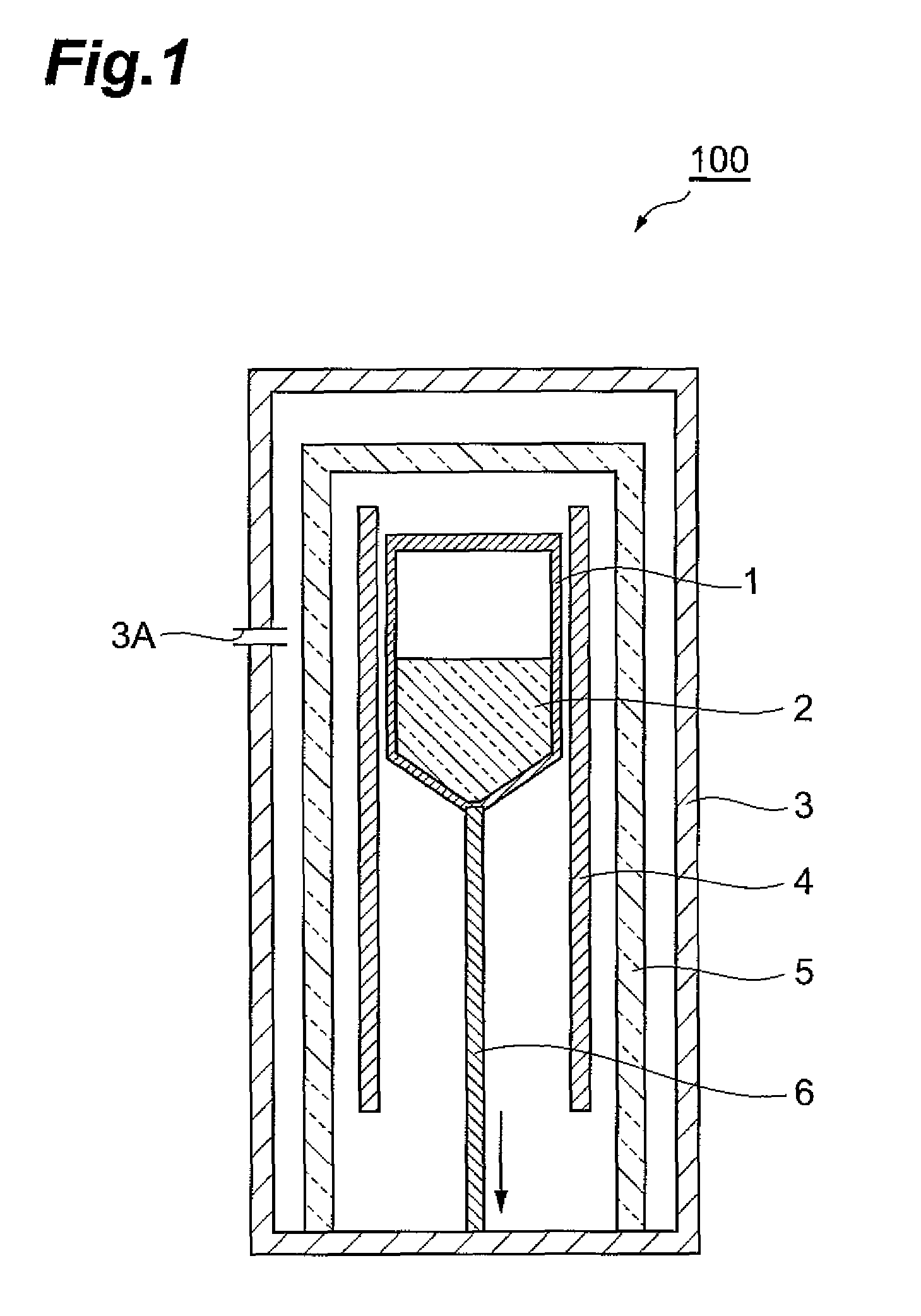
[0072]The obtained mixture was loaded into a quartz ampule, and the interior of the quartz ampule was reduced in pressure to 1 Pa and hermetically sealed in that state. The quartz ampule was then set in a prescribed location of a VB furnace.

[0073]This was followed by single crystal growth by the Bridgman method in the manner described below. First, the heater was heated to 800° C. and the quartz ampule was held for 24 hours in that state to melt the mixture. Th...

example 2

[0074]A single crystal was produced in the same manner as Example 1, except that 5.025 mg of NaBr (99.99% purity, product of Aldrich Co.) was used as the dopant starting material for the scintillator crystal.

example 3

[0075]A single crystal was produced in the same manner as Example 1, except that 5.025 mg of FeBr2 (99.999% purity, product of Aldrich Co.) was used as the dopant starting material for the scintillator crystal.


PUM

PropertyMeasurementUnit
fluorescent wavelengthaaaaaaaaaa
sensitivity wavelength peakaaaaaaaaaa

Abstract

A scintillator crystal represented by the following general formula (1).Ln(1-y)CeyX3:M  (1)wherein Ln(1-y)CeyX3 represents the chemical composition of the matrix material, Ln represents one or more elements selected from the group consisting of rare earth elements, X represents one or more elements selected from the group consisting of halogen elements, M is the constituent element of the dopant which is doped in the matrix material and represents one or more elements selected from the group consisting of Li, Na, K, Rb, Cs, Al, Zn, Ga, Be, Mg, Ca, Sr, Ba, Sc, Ge, Ti, V, Cu, Nb, Cr, Mn, Fe, Co, Ni, Mo, Ru, Rh, Pb, Ag, Cd, In, Sn, Sb, Ta, W, Re, Os, Ir, Pt, Au, Hg, Tl and Bi, and y represents a numerical value satisfying the condition represented by the following inequality (A):0.0001≦y≦1  (A).

Description

BACKGROUND OF THE INVENTION[0001]1. Field of the Invention[0002]The present invention relates to a scintillator crystal and to a radiation detector.[0003]2. Related Background Art[0004]Conventional radiation detectors that comprise scintillators are known as “scintillator-type radiation detectors”. In such radiation detectors, radiation such as γ-rays first interact on the scintillator and generate fluorescence. The generated fluorescence is then detected by a photodetector such as a photomultiplier tube and converted to an electrical signal. The electrical signal is processed by various electronic circuits to obtain information such as the counting rate, fluorescent light quantity and time data. The obtained information is used to determine the intensity, energy and emitting position and direction of the incident radiation. Such scintillator-type radiation detectors are used in a wide variety of fields including, primarily, nuclear medicine, high energy physics, radiation control a...

Claims


Application Information

Patent Timeline
Patent Type & Authority Patents(United States)
IPC IPC(8): G01T1/202C01F17/253
CPCC01F17/0056G01T1/2023C09K11/7772C30B11/00C30B29/12C09K11/7719C01P2002/52C01P2002/54C01P2002/80C01F17/253
Inventor SHIMIZU, SHIGENORINACHIMUTHU, SENGUTTUVANAOSHIMA, MASAHIROSUMIYA, KEIJIISHIBASHI, HIROYUKI
Owner OXIDE
Why Eureka
Try Eureka