Supercharge Your Innovation With Domain-Expert AI Agents!

Friction modifier applicator system for traveling cranes

a technology of friction modifier and applicator system, which is applied in the direction of transportation and packaging, locomotives, hoisting equipment, etc., can solve the problems of limited maximum power available, insufficient alignment of truck wheels, and large use of portal cranes with considerable noise and vibration, etc., to achieve maximum productivity capacity

Inactive Publication Date: 2010-04-13
TRANERGY CORP
View PDF16 Cites 1 Cited by
  • Summary
  • Abstract
  • Description
  • Claims
  • Application Information

AI Technical Summary

Benefits of technology

"The present invention is a friction modifier applicator system for traveling cranes that reduces or eliminates problems such as excessive lateral friction between the crane wheel and rails, which limits the crane's productivity and safety. The system uses an automatic, computer-controlled friction modifier applicator system that sprays a friction modifier on the tread and flanges of the crane's wheel and rail to improve performance. The system includes a nozzle mounted on a truck that sprays the friction modifier, a valve controls the release of the friction modifier, and a sensor measures the performance of the truck to actuate the valve. The system can be used with traveling cranes having four corners and includes a nozzle on each corner truck to spray the friction modifier on the wheel of that truck. The technical effects of the friction modifier applicator system include improved maximum productivity capacity, maximum safety, smooth uninterrupted operation with simultaneous multifunctional ability, and wheel flange / rail wear and durability."

Problems solved by technology

The maximum power available is thus limited to the capacity of the engine-generator combination.
Even on tangent track, portal cranes use much more power with considerable noise and vibration than they need to.
Each truck is free to rotate about its vertical axis, but the rolling direction of the truck wheels is not aligned perfectly when entering a curving rail.
Hence, sharp turns result in the greatest lateral friction force.
This force causes significant rail and wheel flange wear and can cause the flange 23 to break in extreme cases.
In addition to creating an unsafe condition, replacing a wheel on one of these cranes is an expensive process.
In other cases the flange 23 can climb on the rail 18, resulting in a derailment.
Another problem associated with this process is the production of very high levels of noise, which compromises the safety of the workers underneath the crane because of their inability to talk to each other while the crane is moving.
Other problems include excessive vibration and shock to both the electrical and mechanical drive trains and to the whole crane.
Yet another problem is that a major part of the energy of the power plant of the crane is used up in overcoming the wheel-rail contact friction in the lateral direction.
At times, such a large part of the generator current is used to overcome this friction, that only one operating function of the crane can be performed at a time, otherwise the electrical system trips and blowouts can occur.
For example, crane movement cannot occur simultaneously with the rotation of the upper works 10 or lifting of the load, so the capability of rotating the upper works while traveling around the curve (preferred by the operators) is compromised.
Similarly, if the current draw by the truck motors is excessive, the electrical system trips and work is halted until it is fixed.
This can happen in the middle of a load lift, leaving the load hanging in the air.
The above problems are only aggravated by the tendency of the wheels to stick as they slip along the rail which, when combined with the associated large lateral friction, causes the whole crane to vibrate and move jerkily.

Method used


Image

  • Friction modifier applicator system for traveling cranes
  • Friction modifier applicator system for traveling cranes
  • Friction modifier applicator system for traveling cranes

Examples


Embodiment Construction

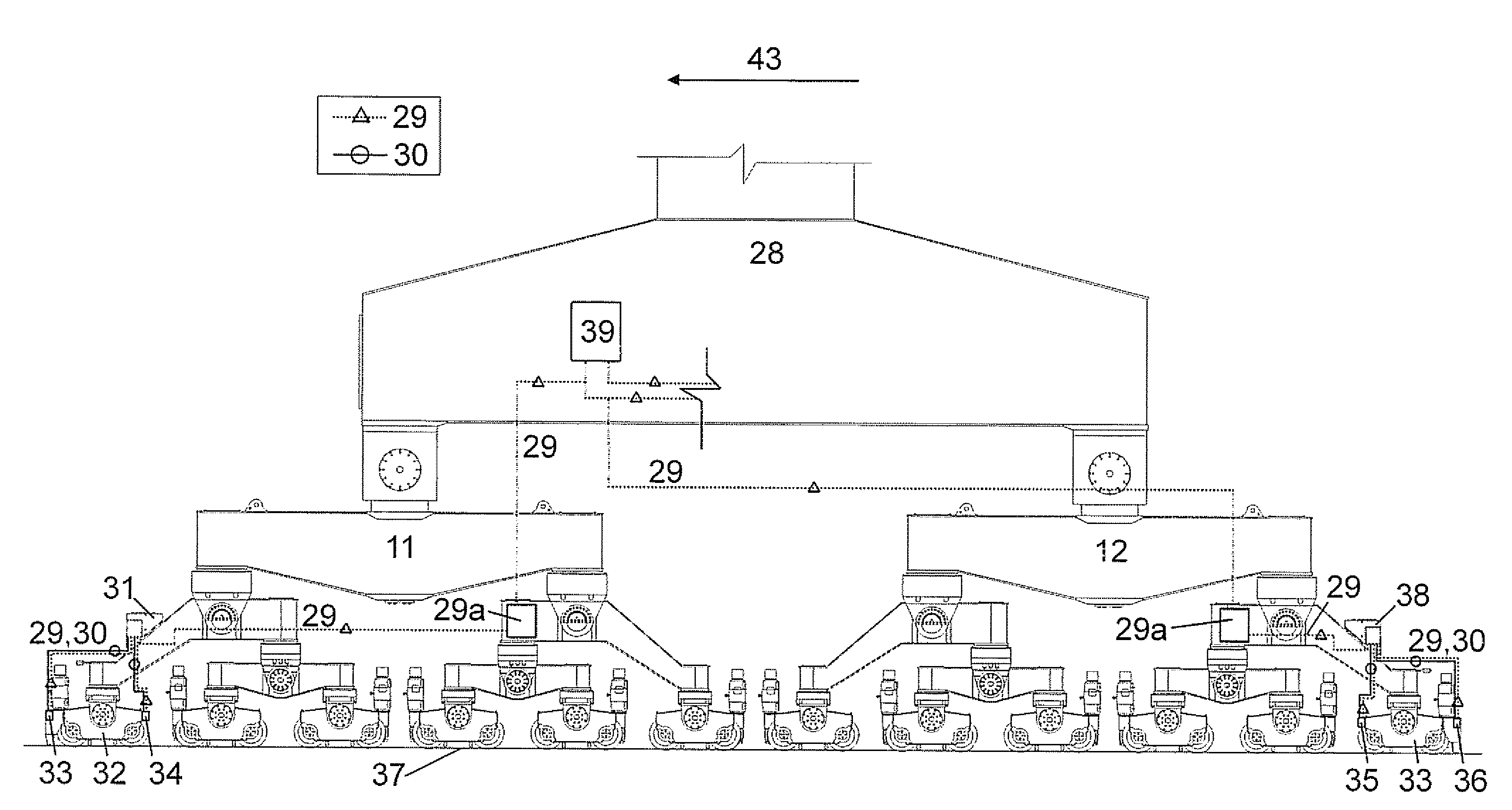
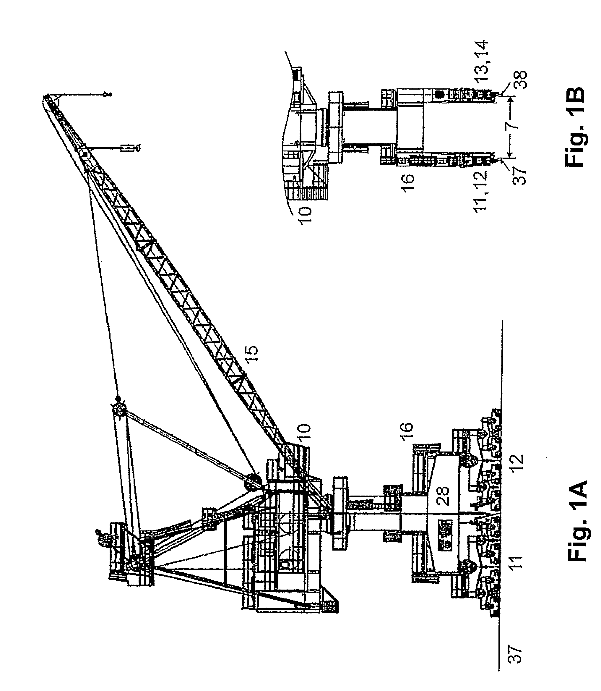
[0028]This invention is a friction management system for improving productivity, safety and operation of traveling cranes, in particular portal cranes, by applying a liquid or solid friction modifier (FM) in precisely controlled quantities to the wheel tread and flanges of one or more wheels of the lead trucks. This reduces the lateral forces, high current draw trips, and high noise levels and improves productivity through increased capacity for number of lifts with the crane.

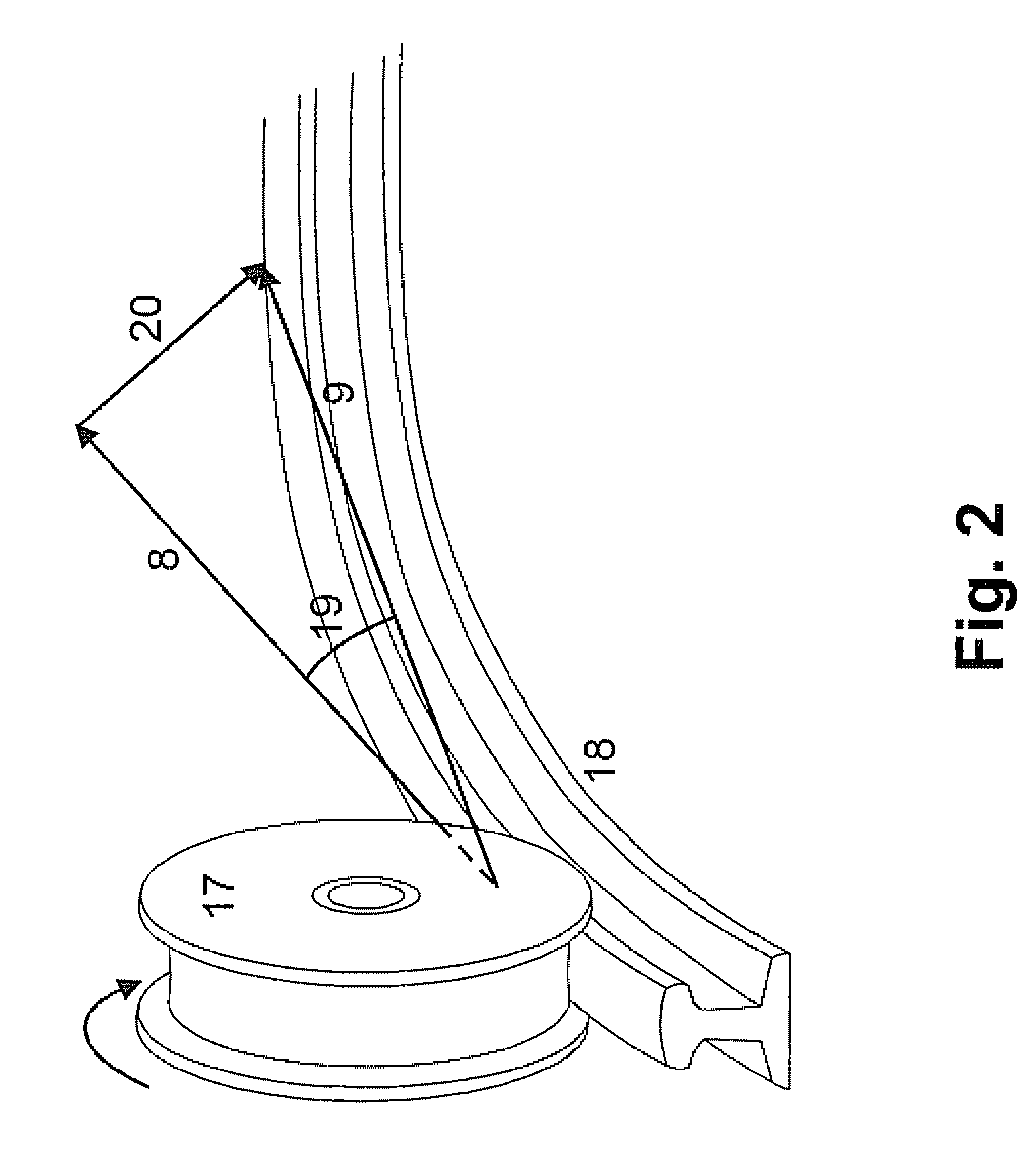
[0029]FIG. 4 shows a crane wheel 17 on a curved rail 18. A friction modifier applicator system, generally designated at 24, includes a solenoid-controlled valve (not shown) and a V-jet nozzle 25. The nozzle 25 is placed at an appropriate distance such that that the spray 26 covers the wheel tread 27 and the two flanges 23. The flat V-shaped spray 26 is applied intermittently by computer control for a specified duration. The FM applied to the wheel 17 transfers to the rail 18 in the region of wheel-rail contact ...


PUM


Abstract

A friction management system for a traveling crane applies a liquid or solid friction modifier (FM) in precisely controlled quantities to the crane wheels or rail to improve performance and safety during movement of the crane. The friction modifier is applied by a nozzle mounted on a crane truck, which nozzle is opened and closed by a valve. The duration of the valve opening per second, which controls the friction modifier application rate, is approximately proportional to the average current draw, which is detected by current sensors connected to the truck motors.

Description

CROSS-REFERENCE TO RELATED APPLICATION[0001]This application claims the benefit of U.S. Provisional Application No. 60 / 746,605, filed May 5, 2006.BACKGROUND OF THE INVENTION[0002]This invention generally relates to traveling cranes. More particularly, this invention relates to systems for reducing friction during movement of a traveling crane along rails.[0003]Portal cranes are used extensively in ports to load and unload ships and submarines. These cranes generally have a high load lifting capacity and therefore utilize double flange steel wheel trucks on heavy weight steel rails. The rails have a wide gage (up to 40 ft. or more). Depending on the load lifting capacity, portal cranes have a large number (8 to 16 or more) of two wheel trucks. One-half to one-third of the wheels are powered. Drive motors are generally located on the truck.[0004]FIGS. 1A and 1B show a typical diagram of a modern portal crane 1 used by the U.S. Navy. A superstructure of several levels, which levels inc...

Claims


Application Information

Patent Timeline
Patent Type & Authority Patents(United States)
IPC IPC(8): B60B39/06
CPCB66C9/10B66C5/00
Inventor KUMAR, SUDHIR
Owner TRANERGY CORP
Features
  • R&D
  • Intellectual Property
  • Life Sciences
  • Materials
  • Tech Scout
  • Unparalleled Data Quality
  • Higher Quality Content
  • 60% Fewer Hallucinations
Learn More