Method and system of heating a fluid catalytic cracking unit for overall CO2 reduction

a fluid catalytic cracking unit and cracking technology, applied in the direction of physical/chemical process catalysts, sustainable manufacturing/processing, furnaces, etc., can solve the problems of insufficient heat supply of the regenerator to the fcc reactor, and the interference of coke with the catalytic activity of the catalys

Active Publication Date: 2010-04-20
UOP LLC +1
View PDF90 Cites 4 Cited by
  • Summary
  • Abstract
  • Description
  • Claims
  • Application Information

AI Technical Summary

Problems solved by technology

Coke interferes with the catalytic activity of the catalyst by blocking active sites on the catalyst surface where the cracking reactions take place.
One issue with this solution, however, is that under gasification conditions, the regenerator may not supply enough heat to the FCC reactor for cracking the hydrocarbon feedstock with the catalyst.

Method used


Image

  • Method and system of heating a fluid catalytic cracking unit for overall CO2 reduction
  • Method and system of heating a fluid catalytic cracking unit for overall CO2 reduction
  • Method and system of heating a fluid catalytic cracking unit for overall CO2 reduction

Examples


Embodiment Construction

[0018]Detailed embodiments of the present invention are disclosed herein. It is understood however, that the disclosed embodiments are merely exemplary of the invention and may be embodied in various and alternative forms. The figures are not necessarily to scale; some figures may be configured to show the details of a particular component. Therefore, specific structural and functional details disclosed herein are not interpreted as limiting but merely as a representative basis with the claims and for teaching one skilled in the art to practice the present invention.

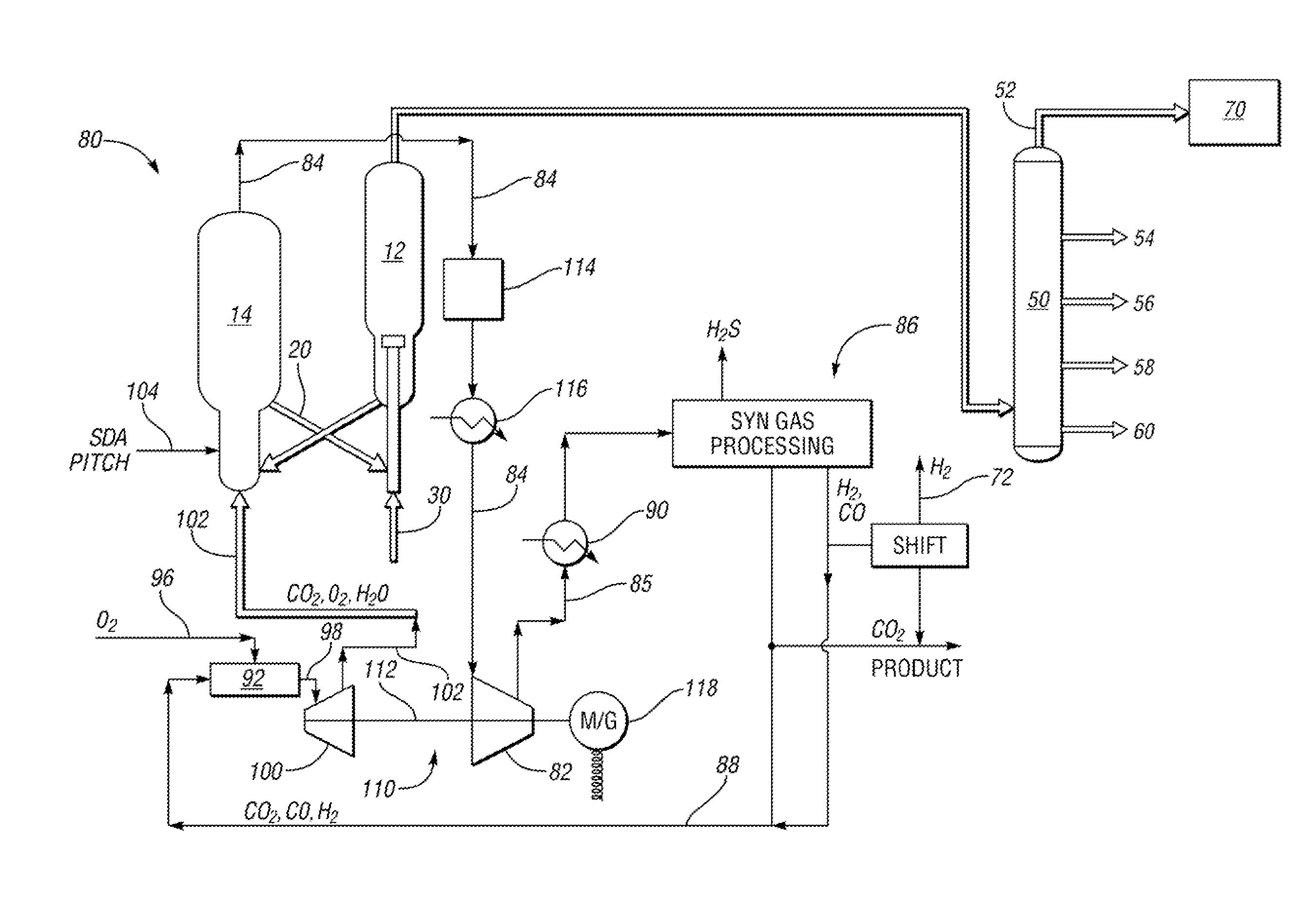
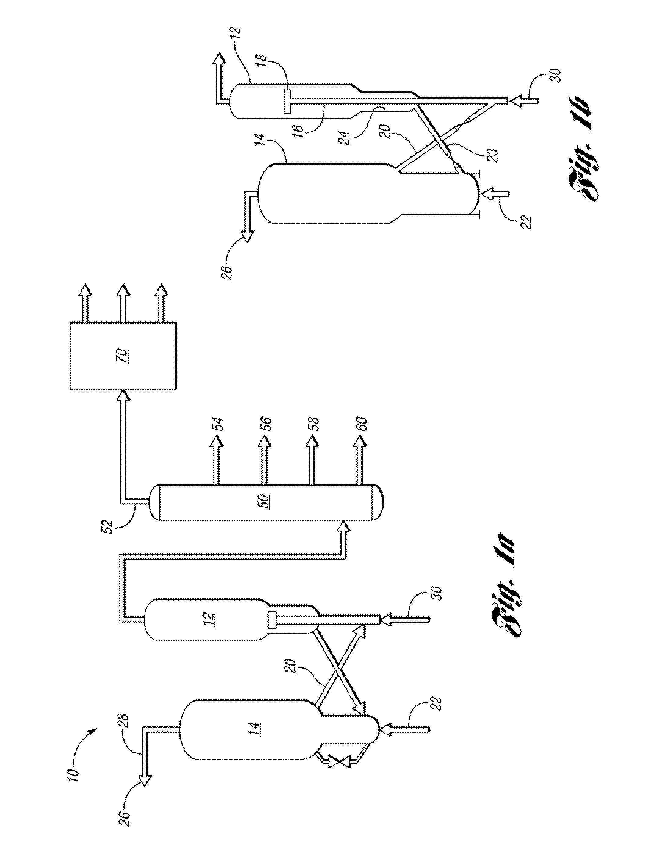
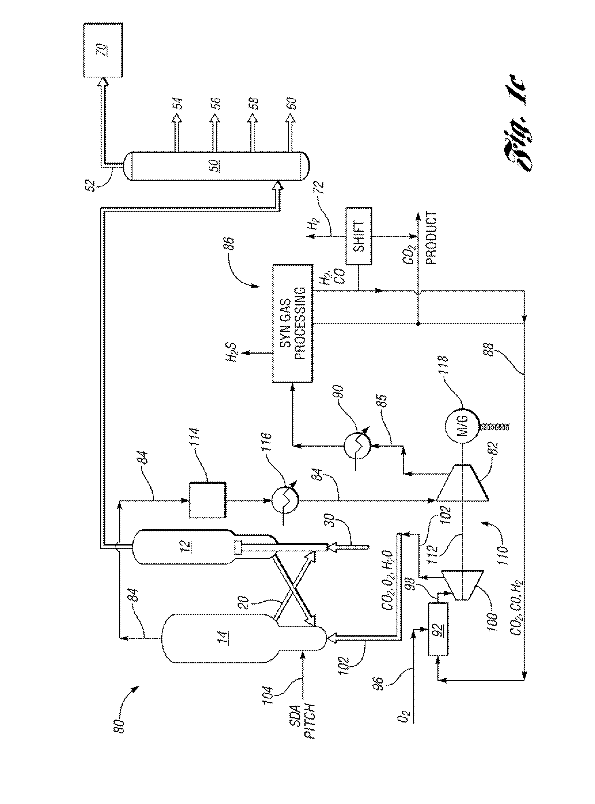
[0019]Examples of the present invention seek to overcome some of the concerns associated with heating a fluid catalytic cracking unit while reducing overall CO2 emissions from the refinery. A conventional fluid catalytic cracking unit burns coke from the spent catalyst by feeding gas comprising air and / or O2 into the regenerator, producing flue gas, which contains CO2 but is typically rich in nitrogen (N2). However, by i...


PUM

PropertyMeasurementUnit
temperatureaaaaaaaaaa
pressureaaaaaaaaaa

Abstract

In at least one embodiment of the present invention, a method of heating a FCC unit having a regenerator and a reactor for over CO2 reduction is provided. The method comprises compressing syngas to define compressed syngas. CO2 is separated from the compressed syngas to provide a first stream of gas comprising CO2. The first stream of gas is expanded with a second stream of gas comprising O2 to define a feed gas. The feed gas and an injected hydrocarbon feed are introduced to the regenerator having spent catalyst from the reactor. The regenerator is at gasification conditions to burn the injected hydrocarbon feed and coke from the spent catalyst producing the syngas and heat for operating the reactor at reaction temperatures.

Description

THE NAMES OF THE PARTIES TO A JOINT RESEARCH AGREEMENT[0001]This application is the result of a joint research agreement between UOP LLC and BP Products North America Inc.BACKGROUND OF THE INVENTION[0002]The present invention relates to methods and systems of reducing carbon dioxide emissions in a fluid catalytic cracking unit.[0003]The fluidized catalytic cracking of hydrocarbons is the mainstay process for the production of gasoline and light hydrocarbon products from heavy hydrocarbon charge stocks such as vacuum gas oils (VGO) or residual feeds. Large hydrocarbon molecules associated with the heavy hydrocarbon feed are cracked to break the large hydrocarbon chains thereby producing lighter hydrocarbons. These lighter hydrocarbons are recovered as product and can be used directly or further processed to raise the octane barrel yield relative to the heavy hydrocarbon feed.[0004]The basic equipment or apparatus for the fluidized catalytic cracking (FCC) of hydrocarbons has been in ...

Claims


Application Information

Patent Timeline
Patent Type & Authority Patents(United States)
IPC IPC(8): C10G51/04
CPCB01J29/90C01B3/26C01B3/30C10G11/182C10G11/185C10J3/482F01K13/00B01J38/30Y02P30/30C01B2203/0277C01B2203/0283C01B2203/0415C01B2203/043C01B2203/0465C01B2203/0475C01B2203/0485C01B2203/0811C01B2203/0822C01B2203/0883C10J2300/16C10J2300/1618C10J2300/1671Y02P20/584Y02P30/446Y02P20/128Y02P20/52Y02E20/34Y02P20/10Y02P30/40Y02P30/00
Inventor HEDRICK, BRIAN W.
Owner UOP LLC
Why Eureka
Try Eureka