
Storage system and a method for dissolving fault of a storage system

a storage system and fault technology, applied in the field of storage system and obstacle elimination method of storage system, can solve the problems of inability to consider the load status of the whole storage system, inability to perform load diffusion or the like, and inability to take the load state of other elements other than, so as to achieve efficient evaluation of efficiency

Inactive Publication Date: 2010-04-20
HITACHI LTD
View PDF31 Cites 13 Cited by
  • Summary
  • Abstract
  • Description
  • Claims
  • Application Information

AI Technical Summary

Benefits of technology

The present invention provides a storage system and obstacle elimination method that can consider the load states of each element constituting the storage system, such as host computers, fiber channel switches, and storage devices, and can perform load diffusion or other measures to eliminate obstacles that hindle performance improvement. The storage system includes a management computer for managing the storage system and a performance information collection unit for collecting performance information on the elements of the communication path extending from the host computer to the storage device. The reviewing unit can select a measure that is effective against the obstacle and can present the measure to the user for consideration. The technical effect of the invention is to improve the performance and efficiency of the storage system by optimizing the allocation of logical volumes and eliminating obstacles that hindle performance improvement.

Problems solved by technology

The former conventional technology is unable to take the load states of other elements other than-the storage device into consideration and is not capable of performing load diffusion or the like on the basis of the status of the whole storage system.
The latter patent document discloses only the transfer of data via a bypass when the communication path is down, and is unable to consider the load status of the whole storage system.
In cases where load ubiquity occurs within the storage system and this is an obstacle to the operation, the storage administrator adds a disk on the basis of his or her own experience and changes the logical-volume allocation.
However, there is no guarantee that the change in constitution will be effective in eliminating the ubiquity of the load.
Moreover, the load status of a storage system that requires continuous operation 24 hours, 365 days a year varies from one hour to the next and it is therefore difficult to adapt suitably and rapidly to irregular changes in status at this frequency.

Method used


Image

  • Storage system and a method for dissolving fault of a storage system
  • Storage system and a method for dissolving fault of a storage system
  • Storage system and a method for dissolving fault of a storage system

Examples


Embodiment Construction

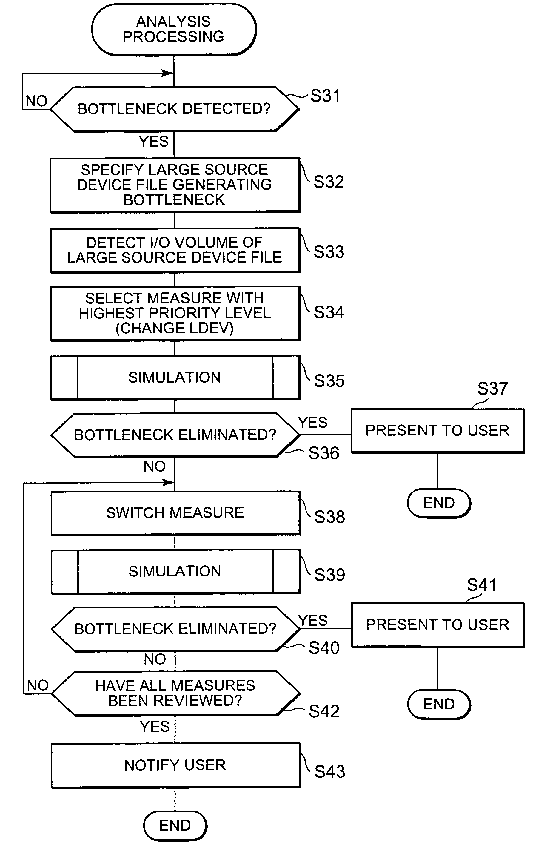
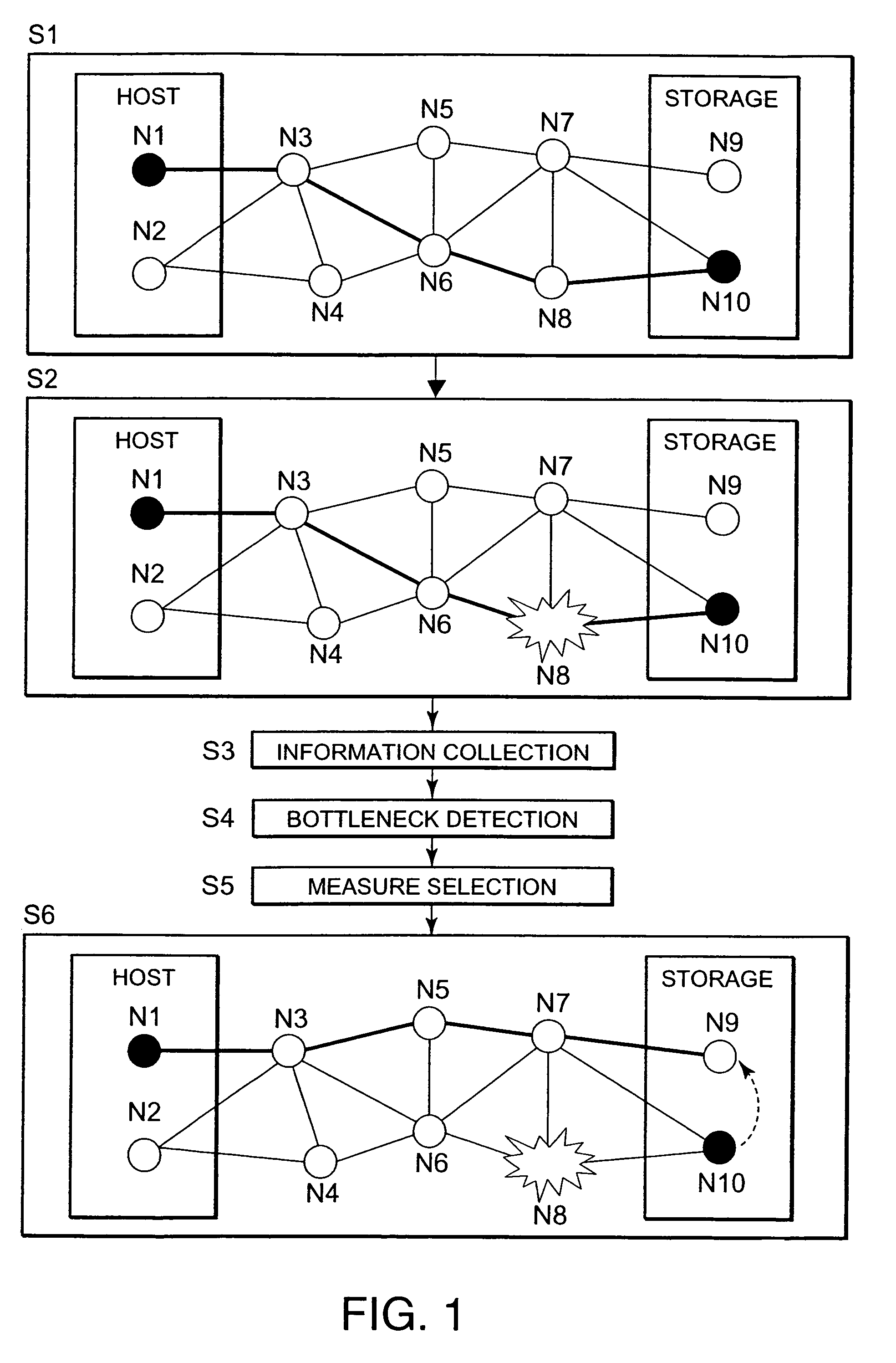
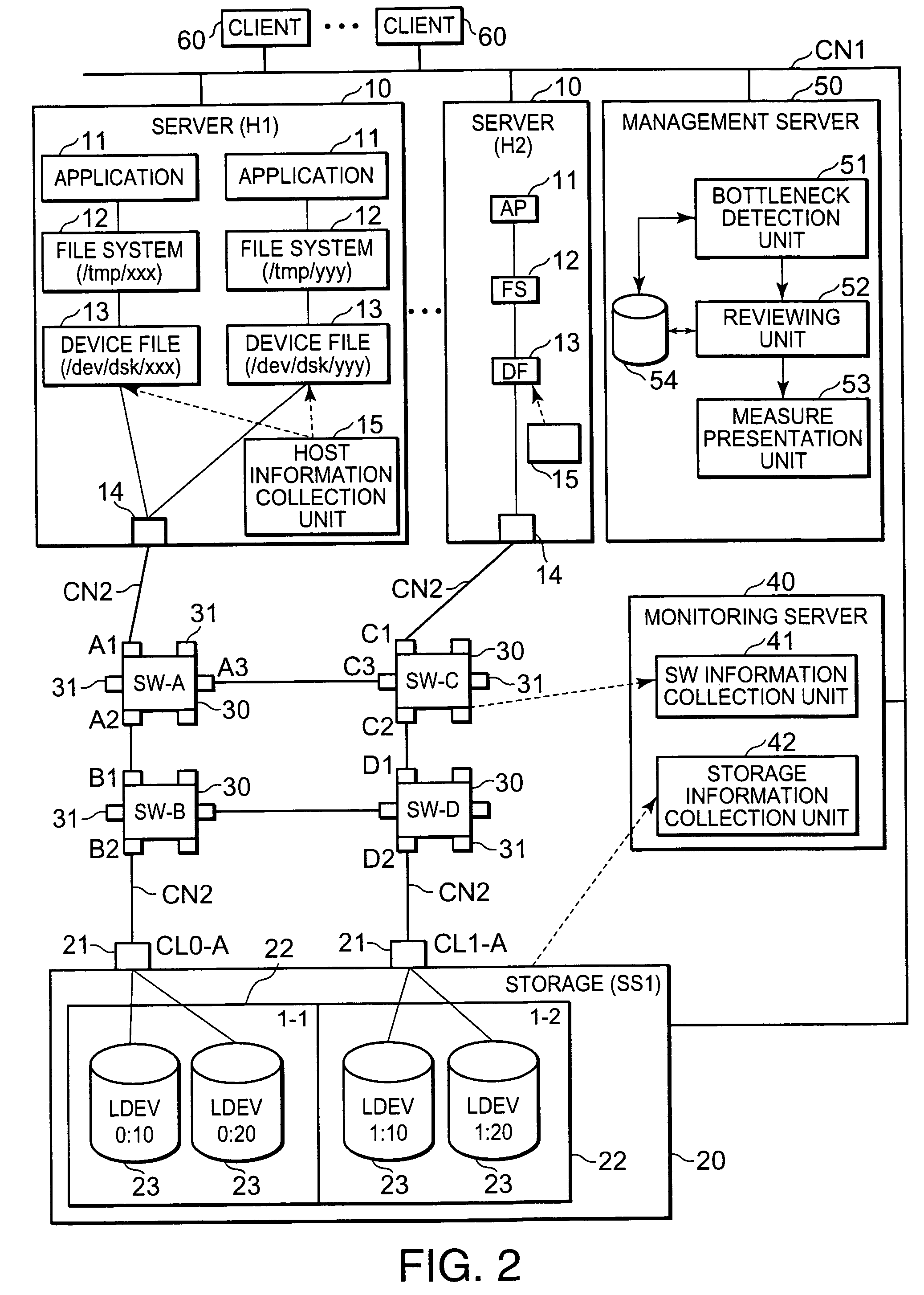
[0041]An embodiment of the present invention will be described below with reference to the drawings. The storage system of the present embodiment is an information processing system having a plurality of data storage elements for storing data (logical volumes, for example), a plurality of data usage elements (device files, for example) for accessing the data stored in the respective data storage elements, at least one or more relay elements (switches, for example) provided between the respective data storage elements and the respective data usage elements, and a path that extends from the respective data usage elements to the respective data storage elements via the relay elements.

[0042]Further, the storage system can comprise a performance information collection unit; a faulty element detection unit; a reviewing unit; and a presentation unit. The performance information collection unit collects information on the performance of the respective elements such as the load state thereof...


PUM


Abstract

The present invention detects the occurrence of a bottleneck on the basis of the states of respective elements of the storage system and presents a measure for eliminating the bottleneck before actually changing the constitution of the storage system. The host element N1 is connected to the element N10 in the storage device via the elements N3, N6 and N8 (S1). Element N1 is a device file or the like, for example. Element N10 is a logical volume or the like, for example. When a bottleneck occurs in the intermediate element N8 (S2), the bottleneck is detected (S4) on the basis of collected information on the respective elements of the storage system (S3). A measure that is effective in eliminating the bottleneck is then reviewed and selected (S5, S6). This measure manipulates any of the elements N1 and N2 or N9 and N10 located at the two ends of the path.

Description

CROSS-REFERENCE TO RELATED APPLICATIONS[0001]This application relates to and claims priority from Japanese Patent Application No. 2004-125622 filed on Apr. 21, 2004, the entire disclosure of which is incorporated herein by reference.BACKGROUND OF THE INVENTION[0002]The present invention relates to a storage system and obstacle elimination method for the storage system.[0003]A storage system comprises one or more storage devices that are used by a plurality of host computers (servers or similar), for example. Respective host computers and storage devices are connected via a relay device such as a fiber channel switch, hub, or the like.[0004]A storage device can also be called a disk array device or the like, for example, and is constituted by arranging a multiplicity of disk drives in the form of an array. Storage devices provide a RAID (Redundant Array of Independent Inexpensive Disks)-based storage area, for example. A logical volume (logical device), which is a logical storage are...

Claims


Application Information

Patent Timeline
Patent Type & Authority Patents(United States)
IPC IPC(8): G06F11/00G06F11/26G06F3/06G06F13/10G06F12/00
CPCG06F11/0727G06F11/0751G06F11/3433G06F11/349
Inventor NUMANOI, TADASHI
Owner HITACHI LTD
Learn More