Electric double-layer capacitor and method for manufacturing the same

a double-layer capacitor and capacitor technology, applied in the field of electric double-layer capacitors, can solve the problems of deterioration in characteristic but also occurrence of gas generation, large cost burden, and increase in inner pressure, and achieve the effects of reducing the number of polarized electrode layers, and reducing the number of polarized electrodes

Active Publication Date: 2010-04-27
PANASONIC CORP
View PDF12 Cites 6 Cited by
  • Summary
  • Abstract
  • Description
  • Claims
  • Application Information

AI Technical Summary

Benefits of technology

[0014]The present invention is an electric double-layer capacitor excellent in long-term reliability which solves the conventional problem as described above, thereby suppressing gas generation in the inside thereof.
[0016]In the electric double-layer capacitor of the present invention, the polarizable electrode layer is formed on both sides of the current collector, and further, the polarizable-electrode-layer-removed section as the exposed portion of the current collector on the periphery of the position where the lead wire is fixed is formed with the minimum required size, whereby it is possible to provide an electric double-layer capacitor and a manufacturing method thereof, the capacitor being excellent in long-term reliability and having electrodes where contact resistance is small and gas generation is suppressed while manufacturing cost is suppressed.
[0018]The method for manufacturing an electric double-layer capacitor according to the present invention can make removal of the polarizable electrode layer extremely easier than the method of scattering the binder components in the polarizable electrode layer and then scraping away the polarizable electrode layer by use of the brush. In addition to that, since the method makes it possible to remove only the portion required to be removed with accuracy, the polarizable electrode layer only with the minimum required area is removed and the lead wire is connected thereto so that the unnecessary exposed portion of the current collector can be extremely small. Hence there can be extremely few cases where BF4−, PF6− and the like as electrolytic anions having generated in the exposed portion of the current collector of the cathode electrode are concentrated to be acidified. This allows suppression of deterioration in separator and thereby allows suppression of gas generation which occurs through an electrochemical reaction, an increase in resistance and a decrease incapacitance, so that an electric double-layer capacitor with small characteristic deterioration and high reliability can be stably manufactured.

Problems solved by technology

However, when a requirement for ensuring a range (70° C., 2.7 V), which exceeds a range (60° C., 2.3 V or less) required of the conventional electric double-layer capacitor to ensure, is intended to be met, there is a problem as follows due to occurrence of such an exposed portion of current collector 125.
Hence there is a problem of consequently causing not only deterioration in characteristic but also occurrence of gas generation and an increase in inner pressure.
It is possible to solve such a problem all at once by forming polarizable electrode layer 126 on the lead wire and exposed portion of current collector 125 after connection of the lead wire to each electrode, but adding such a process forces a large burden in terms of cost.

Method used


Image

  • Electric double-layer capacitor and method for manufacturing the same
  • Electric double-layer capacitor and method for manufacturing the same
  • Electric double-layer capacitor and method for manufacturing the same

Examples


embodiment 1

[0032]In the following, Embodiment 1 of the present invention is described with reference to FIGS. 1 to 5.

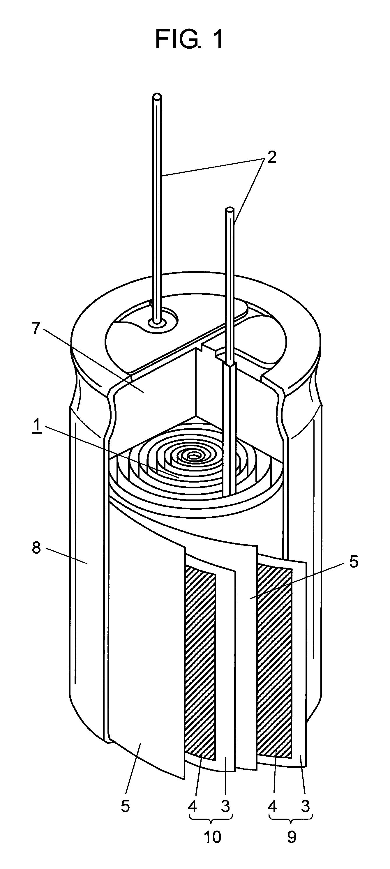
[0033]FIG. 1 is a partially broken away perspective view showing a configuration of an electric double-layer capacitor according to present Embodiment 1.

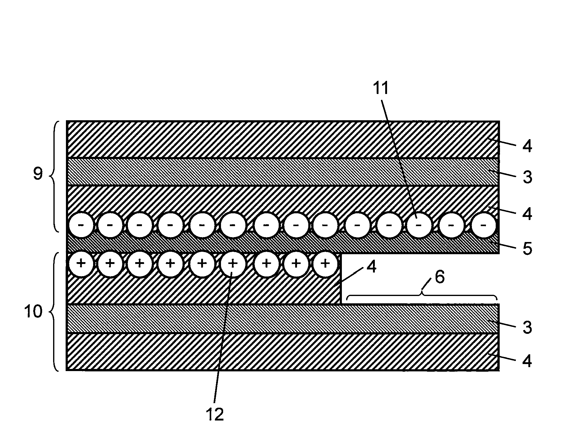
[0034]In FIG. 1, capacitor element 1 is configured such that polarizable electrode layers 4 are formed on both sides of each of two current collectors 3 made of metallic foil such as aluminum, to which lead wires 2 are connected, to give anode electrode 9 and cathode electrode 10, and these electrodes are wound with separator 5 for preventing a short circuit interposed therebetween.

[0035]It is to be noted that respective pairs of lead wires 2 and separators 5 are prepared so as to correspond to the anode and cathode electrodes.

[0036]This capacitor element 1 is impregnated with a driving electrolyte (not shown), and as shown in FIG. 1, rubber-made sealing member 7 provided with holes through which lead wires 2 are inserted is fit...

embodiment 2

[0057]In the following, Embodiment 2 of the present invention is described with reference to FIG. 6.

[0058]FIG. 6 is a partial plan view at the time when lead wire 22 is brought into contact with current collector 27 in Embodiment 2 of the present invention in a different manner from above Embodiment 1.

[0059]In FIG. 6, for connecting lead wire 22 to each of polarizable electrode layers 21 formed on both sides of current collector 27 made of metallic foil such as aluminum constituting the electrode, polarizable electrode layer 21 in a fixed position of lead wire 22 in flat section 23 is scraped away, and polarizable-electrode-layer-removed section 26 is provided. Thereafter, caulking joints 24 are formed at four points in polarizable-electrode-layer-removed section 26 and flat section 23 of lead wire 22 (two points on the end sides of electrode 20, and two points inside). Further, pressure welding joints 25 are formed at three points on a straight line connecting the caulking joints 2...

embodiment 3

[0062]In the following, the present invention is described with reference to Embodiment 3, but the present invention is not restricted to this embodiment. Further, since a configuration of an electric double-layer capacitor is the same as described in Embodiment 1 with reference to FIG. 1, a description thereof is omitted here.

[0063]FIG. 7 A is a substantial-part plan view showing a configuration of anode electrode 32 used in the same capacitor element 31, and FIG. 7 B is a sectional view of a line A-A of the same.

[0064]In FIGS. 7A and 7B, part of polarizable-electrode-layer-removed section 36 formed in anode electrode 32 (the same applies to a polarizable electrode layer formed in a cathode electrode) is removed to expose current collector 35, and to this portion where current collector 35 is exposed, anode lead wire 37 is connected by means of caulking joint and / or pressure welding joint, ultrasonic welding, etc. This removal of polarizable-electrode-layer-removed section 36 is co...


PUM

PropertyMeasurementUnit
heightaaaaaaaaaa
heightaaaaaaaaaa
thicknessaaaaaaaaaa

Abstract

In an electric double-layer capacitor, resistance of a polarizable electrode layer is reduced and gas generation inside a case is suppressed in an attempt to improve reliability. On that account, an electric double-layer capacitor is provided, which is obtained by housing in a case, together with a driving electrolyte, a capacitor element wound with a separator interposed between electrodes being paired anode and cathode electrodes in each of which polarizable electrode layers are formed on and lead wires are fixed to both sides of a current collector made of metallic foil, such that the polarizable electrode layers are opposed to each other. Further, an electric double-layer capacitor is provided in which the lead wire is fixed to a polarizable-electrode-layer-removed section on the electrode where the polarizable electrode layer has been removed, and an area of the polarizable-electrode-layer-removed section is not smaller than 1 and not larger than 2.0 when a project area of a portion where the lead wire is connected with the current collector is set to 1.

Description

TECHNICAL FIELD[0001]The present invention relates to an electric double-layer capacitor used in various electric equipments and a method for manufacturing the same, and particularly relates to an electric double-layer capacitor having excellent low-resistance and low-temperature characteristics and long-term reliability, and a method for manufacturing the same.BACKGROUND ART[0002]FIG. 9 is a partially broken away perspective view showing a configuration of a conventional electric double-layer capacitor of this kind. In FIG. 9, capacitor element 121 is configured by winding anode electrode 122 and cathode electrode 123 in a state where separator 124 is interposed therebetween.[0003]Further, anode electrode 122 and cathode electrode 123 are configured by respectively forming polarizable electrode layers 126 on both sides (the rear side is not shown) of current collector 125 made of metallic foil. Moreover, anode electrode 122 and cathode electrode 123 are respectively connected with ...

Claims


Application Information

Patent Timeline
Patent Type & Authority Patents(United States)
IPC IPC(8): H01G9/00H01G11/28H01G11/86
CPCH01G11/86H01G11/84H01G11/74H01G11/28Y02E60/13Y10T29/417H01G11/26H01G11/70
Inventor HIROSE, ERIITO, YASUYUKIONISHI, SATOMIIWAI, MITSURUYAMAGUCHI, TAKUMIAOKI, ICHIROMORIYAMA, KOUJIHASHIMOTO, YOSHIKI
Owner PANASONIC CORP
Why Eureka
Try Eureka