Capacitor-discharge ignition system for internal combustion engine

a technology of ignition system and capacitor, which is applied in the direction of automatic control of ignition, machines/engines, instruments, etc., can solve the problem of becoming impossible to stop the engin

Active Publication Date: 2010-04-27
HONDA MOTOR CO LTD
View PDF4 Cites 3 Cited by
  • Summary
  • Abstract
  • Description
  • Claims
  • Application Information

AI Technical Summary

Problems solved by technology

However, if wire breakage occurs in the switch circuit, it becomes impossible to stop the engine.

Method used


Image

  • Capacitor-discharge ignition system for internal combustion engine
  • Capacitor-discharge ignition system for internal combustion engine
  • Capacitor-discharge ignition system for internal combustion engine

Examples


first embodiment

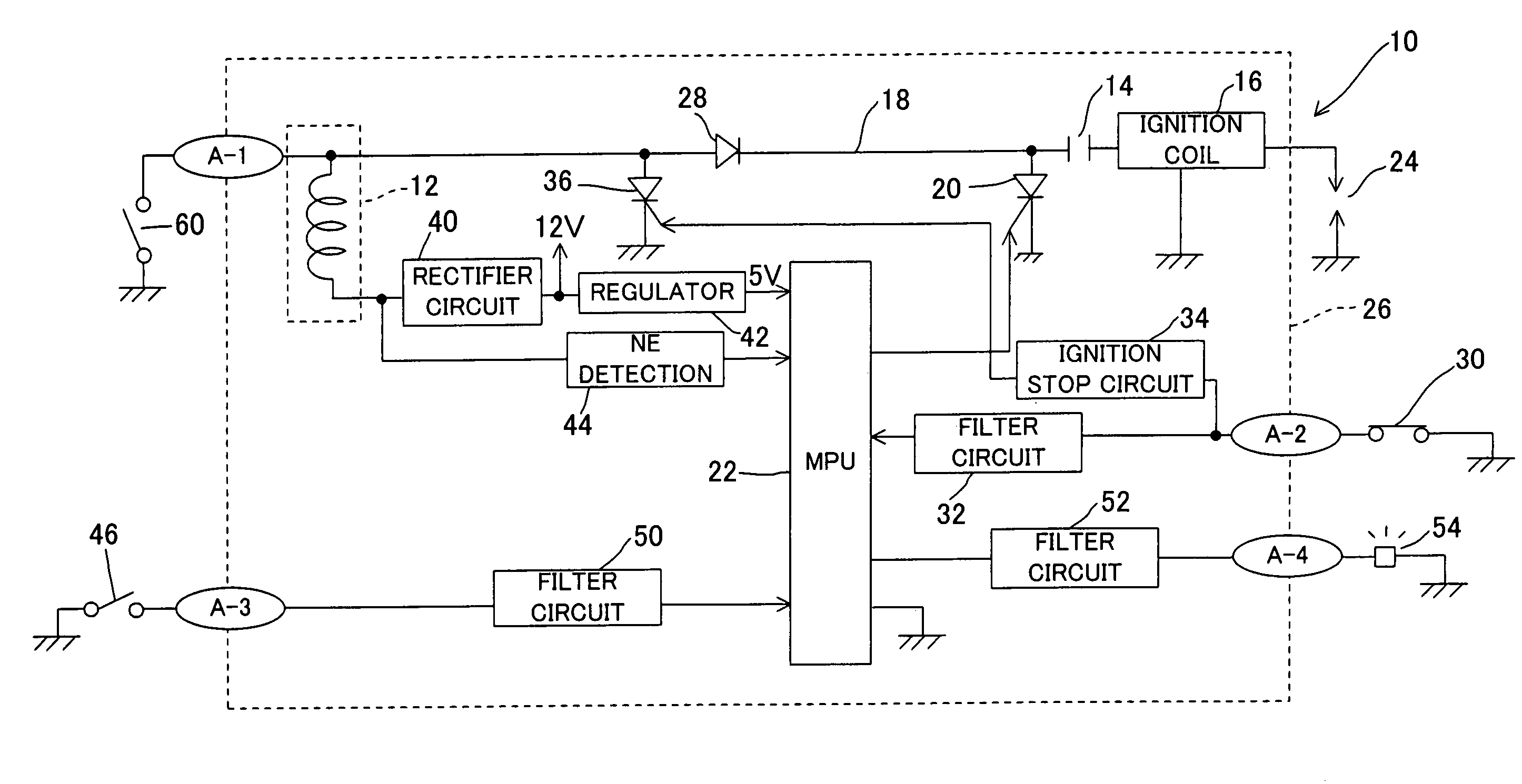
[0013]FIG. 1 is a diagram of the overall capacitor-discharge ignition system for an internal combustion engine according to the invention.

[0014]Reference numeral 10 in FIG. 1 designates a capacitor-discharge ignition (CDI) system for an internal combustion engine. The engine is an air-cooled, four-cycle, single-cylinder OHV model with a displacement of, for example, 390 cc. The engine 10 is suitable for use as the prime mover of electric generators, agricultural machines or any of various other kinds of equipment.

[0015]As illustrated in the figure, the system 10 comprises at least a capacitor 14 that stores an alternating current output produced by an exciter coil (power generation coil) 12, an ignition coil 16 having a primary winding (not shown) connected to the capacitor 14 through a current supply path 18 and a secondary winding (not shown), a first thyristor (switching element) 20 installed in the current supply path 18 from the exciter coil 12 to the primary winding, a micropr...

second embodiment

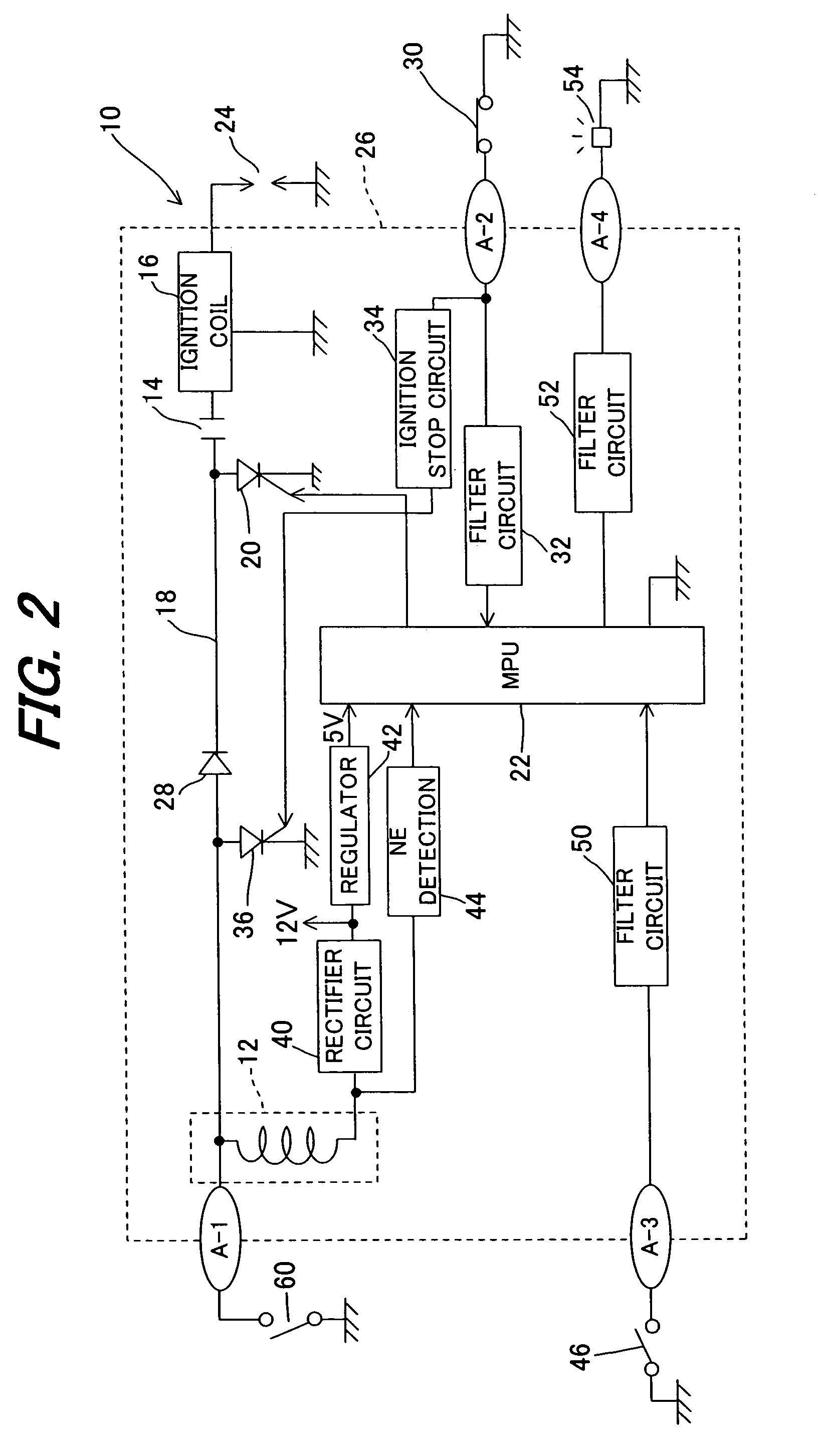
[0036]FIG. 2 is a view, similar to FIG. 1, but showing an overall capacitor-discharge ignition system for an internal combustion engine according to the invention.

[0037]Explaining this with focus on the differences from the first embodiment, a second engine stop switch 60 is added in the second embodiment. The second engine stop switch 60 is connected to the electronic control unit 26 through the terminal A-1 and is connected to the exciter coil 12 at one end, and is grounded at the other end. Similar to the first switch 30, the second engine stop switch 60 is normally closed, i.e., is turned on.

[0038]Thus, in the second embodiment, the system 10 further includes the second engine stop switch 60, installed at a location where the operator can easily manipulate and connected to the exciter coil 12, which grounds the exciter coil 12 to stop the engine when being turned off by the operator.

[0039]With this, the engine can be stopped by either of the engine stop switches 30 or 60. Theref...


PUM


Abstract

In a capacitor-discharge ignition system for an internal combustion engine having a power generation coil, a capacitor connected to the power generation coil, an ignition coil having a primary winding connected to the capacitor through a thyristor and a secondary winding connected to a spark plug, and a microprocessor which turns on the thyristor at a predetermined crank angular position to produce ignition in the spark plug, an engine stop switch is installed to input an engine-stop command signal to the microprocessor when being turned off by the operator. With this, it becomes possible to surely stop the engine at any time if desired.

Description

CROSS REFERENCE TO RELATED APPLICATIONS[0001]The present application claims priority under 35 USC 119 based on Japanese Patent Application JP2007-113393 filed on Apr. 23, 2007, the entire contents of the priority document is incorporated herein by reference.BACKGROUND OF THE INVENTION[0002]1. Field of the Invention[0003]This invention relates to a capacitor-discharge ignition (CDI) system for an internal combustion engine, more particularly to the CDI system for an engine that can surely stop the engine at any time if needed.[0004]2. Description of the Related Art[0005]The CDI system for an internal combustion engine generally includes a power generation coil which is fixed on the engine body inside a rotating flywheel to generate electric power when crossing the fluxes of magnets fastened on the inner wall of the rotating flywheel, and a capacitor which stores the electric power produced by the power generation coil. When a switching element such as thyristor is turned on, the char...

Claims


Application Information

Patent Timeline
Patent Type & Authority Patents(United States)
IPC IPC(8): F02P5/15F02P3/06
CPCF02P3/0846F02P11/00F02P11/025
Inventor NISHIDA, KAZUTOMOKANAI, MITSUYOSHITANIGUCHI, KENTAROKASAI, AKIHITO
Owner HONDA MOTOR CO LTD
Why Eureka
Try Eureka